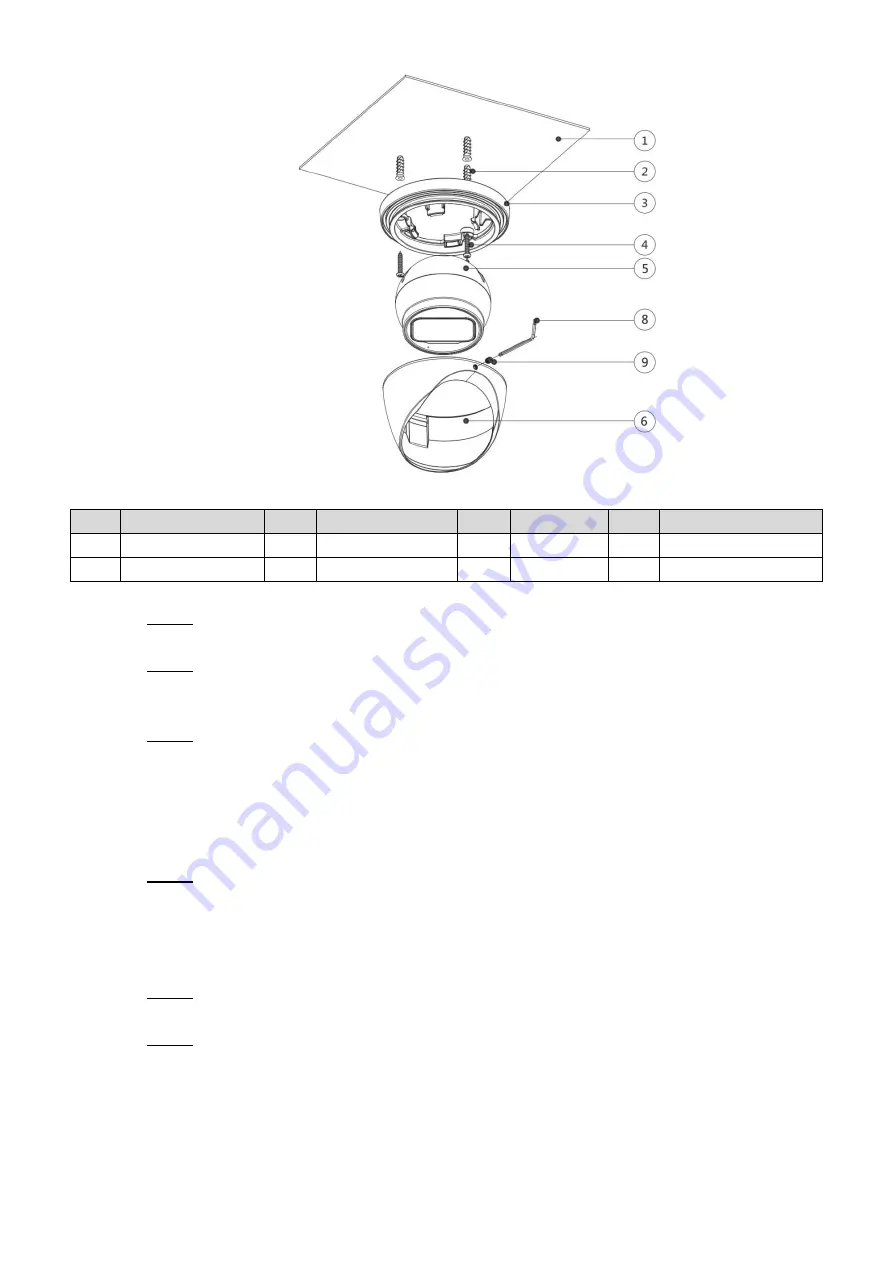
Dahua HDW2501TP-Z-A Скачать руководство пользователя страница 12

Installation    6 


Figure 3-2

No. 

Item 

No. 

Item 

No. 

Item 

No. 

Item 


Mounting surface 


Expansion bolt 


Pedestal 


Self-tapping screw 


Device 


Enclosure 


Wrench 


Locking screw 

Table 3-2  

  Find the mounting template sticker from the accessory pack and stick it to the mounting 

Step 1

surface


  Drill  screw  holes  (and  the  cable  outlet  hole  if  it  needs  to  go  through  the  mounting 

Step 2

surface)  on  the  mounting  surface  as  indicated  on  the  mounting  template,  then  insert 

expansion bolts


from the accessory pack in the screw holes. 

  The disassembly way of model A is different from which of model B and model C. 

Step 3


For model A, hold the pedestal

  tightly and keep the device

  upward, rotate the 

fixing ring

  counterclockwise until you can detach it from above, and then take off 

the pedestal

.     


For model B and model C, loosen the locking screw

 with the supplied wrench


and take the pedestal

  off. 

  Adjust the location of the pedestal

  according to cable outlet requirement (top out or 

Step 4

side out), then pull the cable out through mounting surface or the side cable tray. Align 

the screw holes on the pedestal

 to those on the mounting surface, then put in and 

fasten  the  supplied  self-tapping  screws

  to  attach  the  device

  to  the  mounting 

surface. 

  Connect the camera to power source and the XVR device, and the live view screen will 

Step 5

be displayed.   

  The assembly and adjustment way of model A is different from which of model B and 

Step 6

model C. 


For  model  A,  put  the  fixing  ring

  back  to  hold  the  enclosure

,  leave  some 

spaces enough for you to adjust the device

. Aim the lens to the ideal angle (see 

Figure 3-3) and fasten the fixing ring

Содержание HDW2501TP-Z-A

Страница 1: ...HDCVI Eyeball Camera User s Manual V1 0 1...

Страница 2: ...017 10 Privacy Protection Notice As the device user or data controller you might collect personal data of others such as face fingerprints car plate number Email address phone number GPS and so on You...

Страница 3: ...There still might be deviation in technical data functions and operations description or errors in print If there is any doubt or dispute please refer to our final explanation Upgrade the reader softw...

Страница 4: ...or responsibility for all the fires or electrical shock caused by improper handling or installation Environment Do not aim the device at strong light to focus such as lamp light and sun light Transpor...

Страница 5: ...or the device otherwise it might damage the device When the camera is in the condition of PoC power supply do not connect any other device between the camera and PoC transceiver including UTC Balun op...

Страница 6: ...ontents Foreword I 1 Introduction 1 1 1 General 1 1 2 Features 1 2 Design 2 2 1 Dimension 2 2 2 Cable 3 3 Installation 5 4 Configuration 8 4 1 Opening Main Menu 8 4 2 Setting Audio Input 9 4 3 Operati...

Страница 7: ...zero lag transmission of the signal They are applicable to cover the high definition monitoring needs for locations like financial center telecom site supermarket hotel government school and factory...

Страница 8: ...Design 2 2 Design 2 1 Dimension Model A mm in Figure 2 1 Model B mm in Figure 2 2 Model C mm in Figure 2 3...

Страница 9: ...e information about cable ports see Table 2 1 for the operation method of DIP switch see Table 2 2 No Port Name Function DC 12V Power Input Inputs DC 12V power Please be sure to supply power as instru...

Страница 10: ...utput Connects to XVR to output video signal Audio Input Connects to sound pick up devices to receive analog audio signal Power Output Supplies DC12V 2W power DIP Switch Dial switches to change output...

Страница 11: ...e is for reference only and the actual product shall prevail For the installation diagram and item list of model A see Figure 3 1 and Table 3 1 for those of model B and model C see Figure 3 2 and Tabl...

Страница 12: ...l you can detach it from above and then take off the pedestal For model B and model C loosen the locking screw with the supplied wrench and take the pedestal off Adjust the location of the pedestal ac...

Страница 13: ...device Aim the lens to the ideal angle and adjust the focus until you get clear image see Figure 3 4 and fasten the locking screw Figure 3 4 For model B and model C it is easier to fit the enclosure...

Страница 14: ...nfigure your camera The number of the coaxial port on XVR will display at the lower left corner of the live view window to indicate the corresponding camera 4 1 Opening Main Menu In the live view scre...

Страница 15: ...previous menu until you goes back to the live view screen interface 4 2 Setting Audio Input Audio signal acquisition is available on select models In the Main Menu interface Figure 4 2 select CAMERA...

Страница 16: ...More Setting interface is displayed See Figure 4 4 Figure 4 4 In the More Setting interface you can configure the audio settings Step 4 Enable Audio Encode function In the Audio Format list leave to...

Страница 17: ...interface is displayed See Figure 4 5 Figure 4 5 Click to see more options See Figure 4 6 Step 3 Figure 4 6 Click Step 4 The MENU OPERATION panel is displayed See Figure 4 7 The OSD menu of the corres...

Страница 18: ...t level of this item Click Return to go back to the previous level Clicking Cancel is to exit OSD menu without saving the modifications Interfaces of different XVR might vary and the actual product sh...

Страница 19: ...siccant Maintaining Lens and Mirror Surface The lens and mirror surface are covered with antireflection coating which could be contaminated or damaged and result in lens scratches or haze image when b...

Отзывы: