


134
Icon
Name
Function
USB2.0 port
Connect to peripheral USB 2.0 storage device,
mouse, burner and etc.
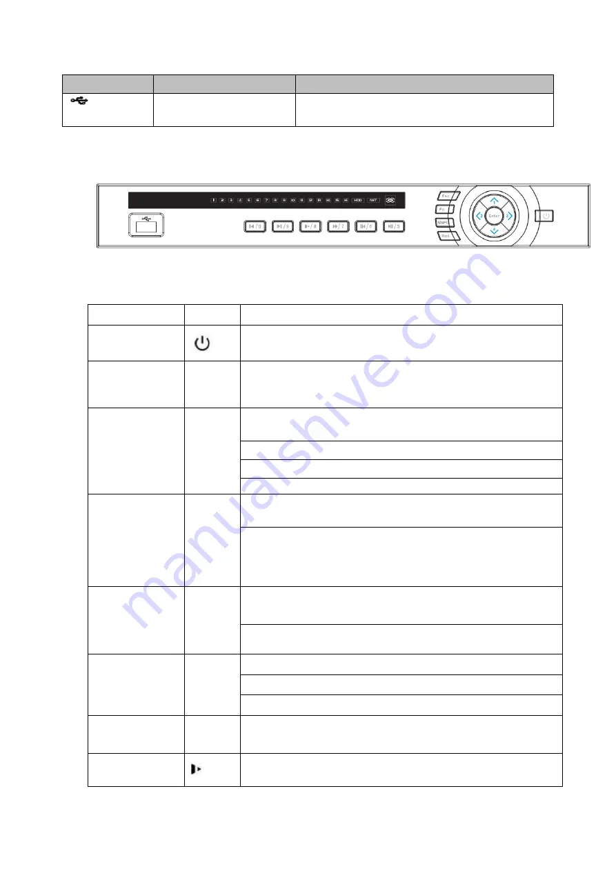
2.1.5 HCVR52XXA-V2/ HCVR72XXA-V2 Series
The front panel is shown as below. See Figure 2-5.
Figure 2-5
Please refer to the following sheet for front panel button information.
Name
Icon
Function
Power button
Power button, press this button for three seconds to boot up
or shut down DVR.
Shift
Shift
In textbox, click this button to switch between numeral,
English(Small/Capitalized),donation and etc.
Up/1Down/4
、
Activate current control, modify setup, and then move up and
down.
Increase/decrease numeral.
Assistant function such as PTZ menu.
In text mode, input number 1/4 (English character G/H/I)
Left/2
Right/3
Shift current activated control,
When playback, click these buttons to control playback bar.
In text mode, input number 2(English character A/B/C)
/3(English character D/E/F)
ESC
ESC
Go to previous menu, or cancel current operation.
When playback, click it to restore real-time monitor mode.
Enter
ENTER
Confirm current operation
Go to default button
Go to menu
Record
REC
Manually stop/start recording, working with direction keys
or numeral keys to select the recording channel.
Slow play/8
Multiple slow play speeds or normal playback.
In text mode, input number 8 (English character T/U/V).
Содержание HCVR2108C-S2 Series
Страница 1: ...Dahua HDCVI Standalone DVR User s Manual Dahua HDCVI Standalone DVR User s Manual V1 8 2 ...
Страница 11: ...x APPENDIX F COMPATIBLE WIRELESS MOUSE LIST 479 APPENDIX G EARTHING 480 ...
Страница 291: ...278 Figure 4 72 Figure 4 73 ...
Страница 322: ...309 Figure 4 105 Figure 4 106 ...
Страница 323: ...310 Figure 4 107 Figure 4 108 ...
Страница 339: ...326 Figure 4 125 Figure 4 126 ...
Страница 340: ...327 Figure 4 127 Figure 4 128 ...
Страница 341: ...328 Figure 4 129 Figure 4 130 ...
Страница 344: ...331 Figure 4 134 Figure 4 135 ...
Страница 351: ...338 Figure 4 145 Figure 4 146 4 11 4 1 2 2Trigger Snapshot ...
Страница 353: ...340 Figure 4 148 Figure 4 149 4 11 4 1 2 3Priority ...
Страница 370: ...357 Figure 4 170 For digital channel the interface is shown as below See Figure 4 171 Figure 4 171 ...
Страница 384: ...371 Figure 4 188 ...
Страница 402: ...389 Figure 5 26 5 8 2 Network 5 8 2 1 TCP IP The single Ethernet port interface is shown as in Figure 5 27 ...
Страница 419: ...406 Figure 5 55 Figure 5 56 ...
Страница 432: ...419 Figure 5 71 Figure 5 72 ...
Страница 439: ...426 Figure 5 81 Figure 5 82 Figure 5 83 Please refer to the following sheet for detailed information ...
Страница 482: ...469 448K 196M 512K 225M 640K 281M 768K 337M 896K 393M 1024K 450M 1280K 562M 1536K 675M 1792K 787M 2048K 900M ...


