background image


bidirectional talk function. You can see the button becomes orange after you enabled the bidirectional 

talk function. Click Talk button again to stop the bidirectional talk function.  

Listening Operation 

At the device end, speak via the speaker or MIC, and then you can get the audio at the pc-end.   


1.3.2  PC-end to Device-end  
Device Connection  

First connect the speaker or MIC to the audio input port of the PC, and then connect the earphones to 

the audio output port of the PC. Login the Web and then click the “Talk” button to enable the 

bidirectional talk function. You can see the button became orange after you enabled the bidirectional 

talk function. Click “Talk” button again to stop the bidirectional talk function. Bidirectional talk function 

and on-site listening function can’t be used at the same time for the device. 

Listening Operation 

At the PC end, speak via the speaker or MIC, and then you can get the audio at the device-end. 

1.4


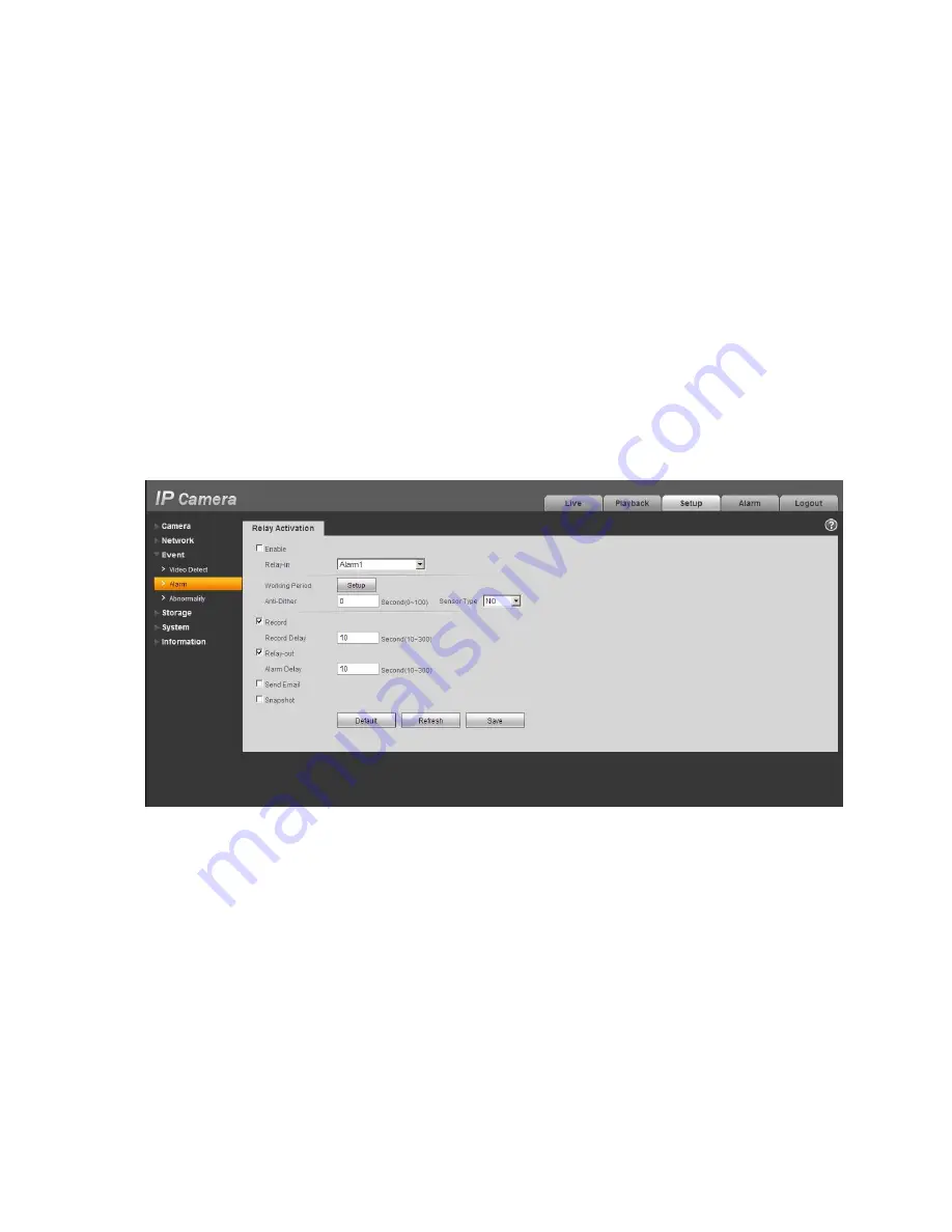
 Alarm Setup  

Please refer to Figure 1-5 for more information about alarm setup. 


Figure 1-5 


Please follow the steps listed below for alarm input and output connection. 

Step 1  Connect the alarm input device to the alarm input port (No.4 pin) of the I/O cable. 

Step 2  Connect alarm output device to alarm output port (No.1pin) and alarm output public port 

(No.2pin), The alarm output port supports NO (normal open) alarm device only.  

Step 3  Open WEB and set corresponding alarm input and output in the alarm setup. Please set the 

alarm input 01 port for the first channel of the I/O cable (No.4 pin). Then set corresponding 

NO/NC input according to the high/low level signal generated when alarm occurs to the alarm 

input device. 

Step 4  Set the WEB alarm output. The alarm output 01 is for the alarm output port of the device. It is 

the No.1 pin of the I/O cable. 


Содержание EBW8600

Страница 1: ...HD Fisheye Panorama Network Camera Quick Start Guide Version 1 1 0 i...

Страница 2: ...esponsibility for all the fires or electrical shock caused by improper handling or installation We are not liable for any problems caused by unauthorized modification or attempted repair 2 Transportat...

Страница 3: ...mponent You can use the blower to clean the dust on the lens surface Always use the dry soft cloth to clean the device If there is too much dust please use the water to dilute the mild detergent first...

Страница 4: ...General Installation 4 2 2 Device Installation Steps 4 2 3 Micro SD Card Installation 5 2 4 Manual Zoom Lens Focus Operation 6 3 Quick Configuration Tool 7 3 1 Overview 7 3 2 Operation 7 4 Web Operati...

Страница 5: ...o signal receive the analog audio signal from the sound pick up 3 LAN Network port Ethernet port Connect to standard Ethernet cable 4 I O I O port Connect I O port 5 POWER Power input port Connect DC...

Страница 6: ...wo standards for side dimension of the device which are 33 7mm 47 7mm and 36 6mm 50 7mm Please refer to the actual product model for more details You can refer to the following figures for dimension i...

Страница 7: ...he same time for the device Listening Operation At the PC end speak via the speaker or MIC and then you can get the audio at the device end 1 4 Alarm Setup Please refer to Figure 1 5 for more informat...

Страница 8: ...tallation information You can see there are installation screws in the accessories bag for you to install the device conveniently Figure 2 1 2 2Device Installation Steps Step 1 Take the installation p...

Страница 9: ...corresponding to the TOP direction on the installation chassis rotate the dome body in clockwise direction and secure it firmly So far installation is completed Note Please refer to Micro SD card inst...

Страница 10: ...sten the screws tightly to prevent dust Figure 2 3 2 4Manual Zoom Lens Focus Operation The lens of the HD panorama dome network camera is 360 no manual zoom is required when it is operated by in ceili...

Страница 11: ...gure 3 1 In the device list interface you can view device IP address port number subnet mask default gateway MAC address and etc Figure 3 1 Select one IP address and then right click mouse you can see...

Страница 12: ...ote the port information here shall be identical with the port value you set in TCP port in Web Network interface Otherwise you cannot login the device If you are using device background upgrade port...

Страница 13: ...rk camera default IP address is 192 168 1 108 Subnet mask is 255 255 255 0 Gateway is 192 168 1 1 Use order ping network camera address to check connection is OK or not 4 2Login and Main Interface Ope...

Страница 14: ...re 4 2 After you successfully logged in please install WEB plug in unit Please refer to the Web Operation Manual included in the resource CD for detailed operation instruction See Figure 4 3 Figure 4...

Страница 15: ...0 degrees panorama Dual picture panorama It is the dual window 180 degrees panorama 1 window It is to display one of the four windows It can show the video around the 360 degrees panorama You can sele...

Страница 16: ...ic or hazardous substance or elements contained in products will not leak or mutate so that the use of these substances or elements will not result in any severe environmental pollution any bodily inj...

Отзывы: