


193
Set preview display mode, channel display sequence and tour setup.
Set preview display mode: On the preview interface, right click mouse, you can view right-click menu.
Now you can select preview window amount and channel.
Set channel display mode: On the preview interface, if you want to change channel 1 and channel 16
position, please right click channel 1 video window and then drag to the channel 16 video window,
release button, you can change channel 1 and channel 16 position.
Tour setup: Here you can set preview window channel display mode and interval. Please follow the
steps listed below.
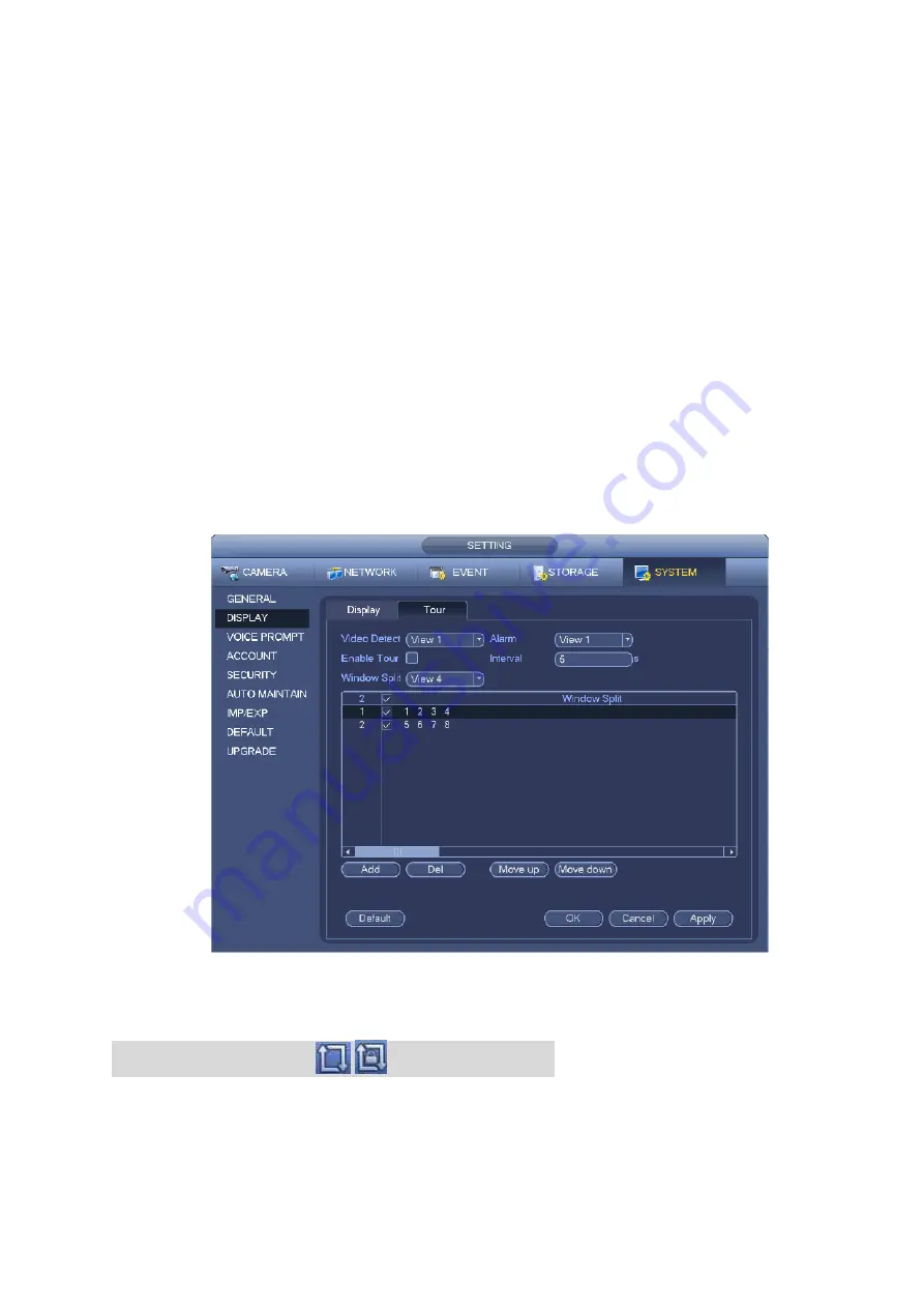
From Main menu->Setting->System->Display->Tour, you can see an interface shown as in Figure 4-74.
Here you can set tour parameter.
Enable tour: Check the box here to enable tour function. The general tour supports all types of
window split mode.
Interval: Input proper interval value here. The value ranges from 1-120 seconds.
Motion tour type: System support 1/8-window tour. Please note you need to go to the main
menu->Setting->Event->Video detect->Motion detect to enable tour function.
Alarm tour type: System support 1/8-window tour. Please note you need to go to the main
menu->Setting->Event->Alarm to enable tour function.
Window split: It is to set window split mode.
Figure 4-74
Tips
On the navigation bar, click
/
to enable/disable tour.
Click Save button to save current setup.
4.3.6.5 Customized split
It is to set customized video split mode.
Содержание DHI-NVR5224-24P-4KS2
Страница 1: ...Network Video Recorder User s Manual V4 3 2...
Страница 136: ...124 Figure 3 5 3 6 6 NVR42N Series Please refer to Figure 3 6 for connection sample Figure 3 6...
Страница 140: ...128 Figure 3 11 3 6 12 NVR42V 8P Series Please refer to Figure 3 12 for connection sample...
Страница 141: ...129 Figure 3 12...
Страница 155: ...143 Figure 4 15 Step 2 Click device display edit interface See Figure 4 16...
Страница 218: ...206 Figure 4 93 Figure 4 94...
Страница 238: ...226 Figure 4 110 Figure 4 111 Figure 4 112...
Страница 249: ...237 Figure 4 123 Figure 4 124...
Страница 251: ...239 Figure 4 126 Click draw button to draw the zone See Figure 4 127...
Страница 255: ...243 Figure 4 130 Click Draw button to draw a zone See Figure 4 131 Figure 4 131...
Страница 260: ...248 Figure 4 136 Click draw button to draw the zone See Figure 4 137...
Страница 273: ...261 Figure 4 148 Figure 4 149...
Страница 274: ...262 Figure 4 150 Figure 4 151...
Страница 384: ...372 Figure 5 60 Figure 5 61...
Страница 385: ...373 Figure 5 62 Figure 5 63...
Страница 409: ...397 Figure 5 96 Figure 5 97...
Страница 415: ...403 Figure 5 106 5 10 4 4 Record Control The interface is shown as in Figure 5 107 Figure 5 107...