background image

User's Manual 

Table 2-1 Protective cover 

No. 

Description 

No. 

Description 

Camera 

Power 

Terminal 

Built-in LED illuminator 
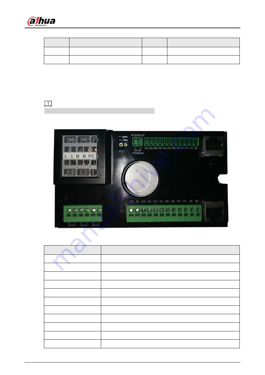
2.2 Terminal 

The two typical kinds of terminals are shown in the following two figures. 


Different devices might have different types of terminals. 

Figure 2-4 Terminal (1) 


Table 2-2 Description of terminal (1) 

Name 

Description 

F1+ 

Flashing light 1 triggers output F1+ 

F1- 

Flashing light 1 triggers output F1- 

F2+ 

Flashing light 2 triggers output F2+ 

F2- 

Flashing light 2 triggers output F2- 

F3+ 

Flashing light 3 triggers output F3+ 

F3- 

Flashing light 3 triggers output F3- 

F4+ 

Flashing light 4 triggers output F4+ 

F4- 

Flashing light 4 triggers output F4- 

F7+ 

Strobe synchronous output F7+ 

F7- 

Strobe synchronous output F7- 

A1 

RS–485_A1 

Содержание DHI-ITC952-RU2F-BD

Страница 1: ...All in one Enforcement Camera User s Manual ZHEJIANG DAHUA VISION TECHNOLOGY CO LTD V1 0 3 ...

Страница 2: ...640 DHI ITC952 RU2F BD ZF1640 ITC952 RU2F BD ZF1640 ITC352 AU3F L ZF1640 ITC352 AF3F 3 MP ITC352 AU3F IRL7 ZF1640 ITC352 AF3F IR7 ITC352 AU3F IRL8 ZF1640 ITC352 AF3F IR8 Safety Instructions The following signal words might appear in the manual Signal Words Meaning Indicates a high potential hazard which if not avoided will result in death or serious injury Indicates a medium or low potential hazar...

Страница 3: ...with the manual The manual will be updated according to the latest laws and regulations of related jurisdictions For detailed information see the paper user s manual use our CD ROM scan the QR code or visit our official website The manual is for reference only Slight differences might be found between the electronic version and the paper version All designs and software are subject to change witho...

Страница 4: ...sures to ensure personal safety including wearing a helmet and safety belts Do not place the device in a place exposed to sunlight or near heat sources Keep the device away from dampness dust and soot Put the device in a well ventilated place and do not block its ventilation Use an adapter or cabinet power supply provided by the manufacturer The power supply must conform to the requirements of ES1...

Страница 5: ...he device is a class I electrical appliance Make sure that the power supply of the device is connected to a power socket with protective earthing The device must be used with the protective cover for outdoor scenarios to avoid the risk of water damage to the device Protect the line cord and wires from being walked on or squeezed particularly at plugs power sockets and the point where they exit fro...

Страница 6: ... Lens 13 3 1 2 Removing the Lens 14 3 2 Installing TF Card 14 3 2 1 Installing the TF Card 14 3 2 2 Removing the TF Card 14 3 3 Connecting Cable 15 3 3 1 Installing the Cable 15 3 3 2 Removing the Cable 16 3 4 Installing Sun Shade 16 3 5 Installing Corrugated Pipe 16 4 System Network 17 5 Configuration 18 5 1 Initialization 18 5 1 1 Initializing Single Camera on Web Page 18 5 1 2 Initializing Came...

Страница 7: ...User s Manual VI Appendix 1 Cybersecurity Recommendations 27 ...

Страница 8: ...sign Embedded component based design Integrated structure that realizes low power consumption High Integration Level The Camera is integrated with high definition camera fill light terminal etc significantly saving on site installation time Excellent Performance High performance multi core process High performance CCD and CMOS image sensors featured by high color reproduction and speed High perfor...

Страница 9: ...ds User permission control Storage Stores the record data on central server according to the storage policy configured by user After recording according to user needs and by web recording mode video files are stored on the client computer Supports TF card local storage hot swapping and ANR When storage space is insufficient it automatically overlays the stored files Alarm Supports sending alarm th...

Страница 10: ...rk Management Supports configuration and permission management through Ethernet Supports managing the Camera by web Extra Device Control Supports peripheral device management The control protocol and port of peripheral device can be configured freely Supporting connection to peripheral devices such as flashlight strobe light vehicle detector signal detector radar and more Power Supply AC synchroni...

Страница 11: ...atermark encryption of video image coding to prevent tampering Real time display of system resource information and running status Support log function Signal control and output of strobe flashing light and continuous light GPS positioning ...

Страница 12: ... Structure Protective cover of the Camera includes power supply terminal and HD camera The structure is taken as an example Different devices might have different components Figure 2 1 Structure Figure 2 2 Structure 2 Figure 2 3 Structure 3 ...

Страница 13: ...inals Figure 2 4 Terminal 1 Table 2 2 Description of terminal 1 Name Description F1 Flashing light 1 triggers output F1 F1 Flashing light 1 triggers output F1 F2 Flashing light 2 triggers output F2 F2 Flashing light 2 triggers output F2 F3 Flashing light 3 triggers output F3 F3 Flashing light 3 triggers output F3 F4 Flashing light 4 triggers output F4 F4 Flashing light 4 triggers output F4 F7 Stro...

Страница 14: ... 2 5 Terminal 2 Figure 2 6 Terminal 3 Table 2 3 Description of terminal 2 Name Description 1 Flashing light 1 triggers output F1 2 Flashing light 1 triggers output F1 3 Flashing light 2 triggers output F2 4 Flashing light 2 triggers output F2 5 Flashing light 3 triggers output F3 6 Flashing light 3 triggers output F3 ...

Страница 15: ...B1 11 12 DC 12 13 12 DC 14 L 220 VAC live wire N 220 VAC neutral wire PE 220 VAC earth wire 2 3 Camera 2 3 1 Rear Panel Figure 2 7 Rear panel Table 2 4 Rear panel ports Port Function DC 12 IN Power input port 12 VDC input SI SI Synchronous input port of external frequency source The camera synchronizes with external signal source ...

Страница 16: ... might burn out A1 B1 RS 485 ports 2 ports connecting to signal detector vehicle detector radar flashing light strobe and other illuminators A2 B2 2 ports connecting to flashing light strobe and other illuminators G GND Ground terminal IN1 IN2 IN3 IN4 IO input 4 IO snapshot ports or 4 alarm input ports AO1 AO2 2 channel alarm output Can be configured respectively as alarm output port and wiper out...

Страница 17: ...mera and click Hot Swap 2 3 2 Side Panel Figure 2 8 Side panel dimensions mm inch 2 3 3 Front Panel Figure 2 9 Front panel dimensions mm inch 2 4 LED Illuminator Different models are designed with different types and numbers of LED illuminators to meet your various needs Models with IR illuminators bring less light pollution and it is more suitable to use ...

Страница 18: ...o models are designed with 3 white light LED illuminators Figure 2 10 Dimensions mm inch DHI ITC952 AU3F IRL7 DHI ITC952 AU3F IRL8 DHI ITC352 AU3F IRL7 DHI ITC352 AU3F IRL8 These models are designed with 8 IR illuminators Figure 2 11 Dimensions mm inch DHI ITC952 RU2D IRL7 DHI ITC952 RU2D IRL8 These two models are designed with 10 built in IR LED illuminators ...

Страница 19: ...User s Manual 12 Figure 2 12 Dimensions mm inch DHI ITC952 RU2F BD No illuminators ...

Страница 20: ...o the actual condition 3 1 Installing Lens Power off the Camera before installing the lens Otherwise the lens might be damaged Figure 3 1 Install the lens 3 1 1 Installing the Lens Step 1 Remove the protective covers of sensor and lens Insert the spacer in between the lens and the camera Step 2 Align the lens to the lens mount position on the camera and turn the lens clockwise until it is securely...

Страница 21: ...to prevent them from being spotted 3 2 Installing TF Card This section takes some models as the example and might differ from the actual model 3 2 1 Installing the TF Card Orient the TF card to make the teeny triangle on the card points toward the open slot and then gently shove the card all the way into the slot Figure 3 3 Installing TF card 3 2 2 Removing the TF Card Remove the TF card according...

Страница 22: ...f the power of the Camera first to avoid leakage This helps prevent personal injury To ensure the Camera is properly grounded and improve device reliability make sure that The device port is connected to the PE earth wire of the protective cover The PE is connected to the ground The picture is for reference only and might differ from the actual device cable Figure 3 5 Cable connection example 1 3 ...

Страница 23: ...4 Installing Sun Shade Figure 3 6 Cable connection example 2 Table 3 1 Sunshade connection description No Description No Description 1 5 Screw 4 Washer 2 PTFE gasket 6 Sunshade 3 Pillar 7 Camera protective cover Step 1 Remove the screws on the top of the camera protective cover Step 2 Fix the pillar to the top of the camera protective cover Step 3 Align the sunshade with the center hole of the pil...

Страница 24: ...Network As the center of traffic surveillance system the Camera can record videos of different surveillance scenes and transmit video data to controller central server or storage device through network Figure 4 1 System network ...

Страница 25: ...ge Step 1 Connect the Camera to network 1 Connect the Camera to PC over the Ethernet cable 2 Keep the IP address of the PC and the camera on the same network segment The network segment can be set to 192 168 1 X but cannot be the same with the factory default IP of the Camera 192 168 1 108 3 Execute ping x x x x device IP command on PC to check network connection Step 2 Enter the IP address of the...

Страница 26: ...fig Guide page set the business type and road mode Business Type You can select from ANPR E Police and Yield to Pedestrians Road Mode Select City Road or High Road expressway according to the actual installation position of the Camera Iris Type Lens Type Only Manual is available Figure 5 3 Config guide 1 Step 10 Click Next and you can start modifying the default IP address of the Camera Figure 5 4...

Страница 27: ... Internet Options Security Custom Level is enabled Step 13 After successfully installing the plug in the live view of the Camera is displayed Figure 5 6 Web page 5 1 2 Initializing Cameras in Batches with ConfigTool It is ideal to initialize cameras in batches and modify their default IP addresses by using ConfigTool To acquire ConfigTool go to Dahua official website and then select Support Downlo...

Страница 28: ... in which you want to search devices and then click OK default IP address of the Camera 192 168 1 108 Step 4 All the devices found in the network segment are listed Step 5 Select cameras with Status showing Uninitialized and then click Initialize Step 6 On the Device initialization page select the devices that need initialization and then click Initialize Step 7 Set and confirm the password of the...

Страница 29: ...3 in 5 1 2 Initializing Cameras in Batches with ConfigTool to search for cameras in your network segment After clicking Search setting enter the username and password and make sure that they are the same as what you set during initialization otherwise there will be Wrong Password notice Step 2 Select the cameras which IP addresses need to be modified and then click Modify IP Figure 5 9 Modify IP A...

Страница 30: ... browser address bar and press the Enter key Step 3 Enter username and password on the displayed page and then click Login A box pops up when the username or password is incorrect See Figure 5 10 If you enter invalid username or password for five times the account will be locked for five minutes Figure 5 10 Invalid username or password Figure 5 11 Devices found page 5 3 Updating the Camera with Co...

Страница 31: ...ect the ITCs cameras that you want to update Update one ITC Click Browse corresponding to the ITC to be updated Update ITCs in batches Select the ITCs to be updated and then click Batch Upgrade Step 4 Select the update file Figure 5 13 Select the upgrade file Step 5 Update the cameras ...

Страница 32: ...starts updating You can view the update progress Update ITCs in batches Click OK and the system starts updating If the camera is disconnected during updating as long as the ConfigTool stays on the update page the update will resume when the connection is restored ...

Страница 33: ...elps ensure data integrity and avoid losing all the data of the card TF card read write limit Do not set the TF card as the storage media of pre set recording It might damage the TF card duration TF card cannot be used as storage media When the TF card hibernates or its capacity is full format the card through web first Recommended TF card It is recommended to use TF card of 16 GB or above This he...

Страница 34: ...ation of firmware updates released by the manufacturer We suggest that you download and use the latest version of client software Nice to have recommendations to improve your equipment network security 1 Physical Protection We suggest that you perform physical protection to equipment especially storage devices For example place the equipment in a special computer room and cabinet and implement wel...

Страница 35: ...nsmission function to reduce the risk of audio and video data being stolen during transmission Reminder encrypted transmission will cause some loss in transmission efficiency 11 Secure Auditing Check online users we suggest that you check online users regularly to see if the device is logged in without authorization Check equipment log By viewing the logs you can know the IP addresses that were us...

Страница 36: ...ress filtering function to limit the range of hosts allowed to access the device More information Please visit Dahua official website security emergency response center for security announcements and the latest security recommendations ...

Страница 37: ...User s Manual ...

Отзывы: