Dahua DHI-ITC215-PW6M-IRLZF Скачать руководство пользователя страница 64

User’s Manual 

53 

Delete 

Click it and delete the latest ROI. It can click for several times. Right click 
any position in the image to realize the same effect. 

Step 3  Click 

Confirm

4.5.3 Network 

You can set IP address, port and other parameters. 
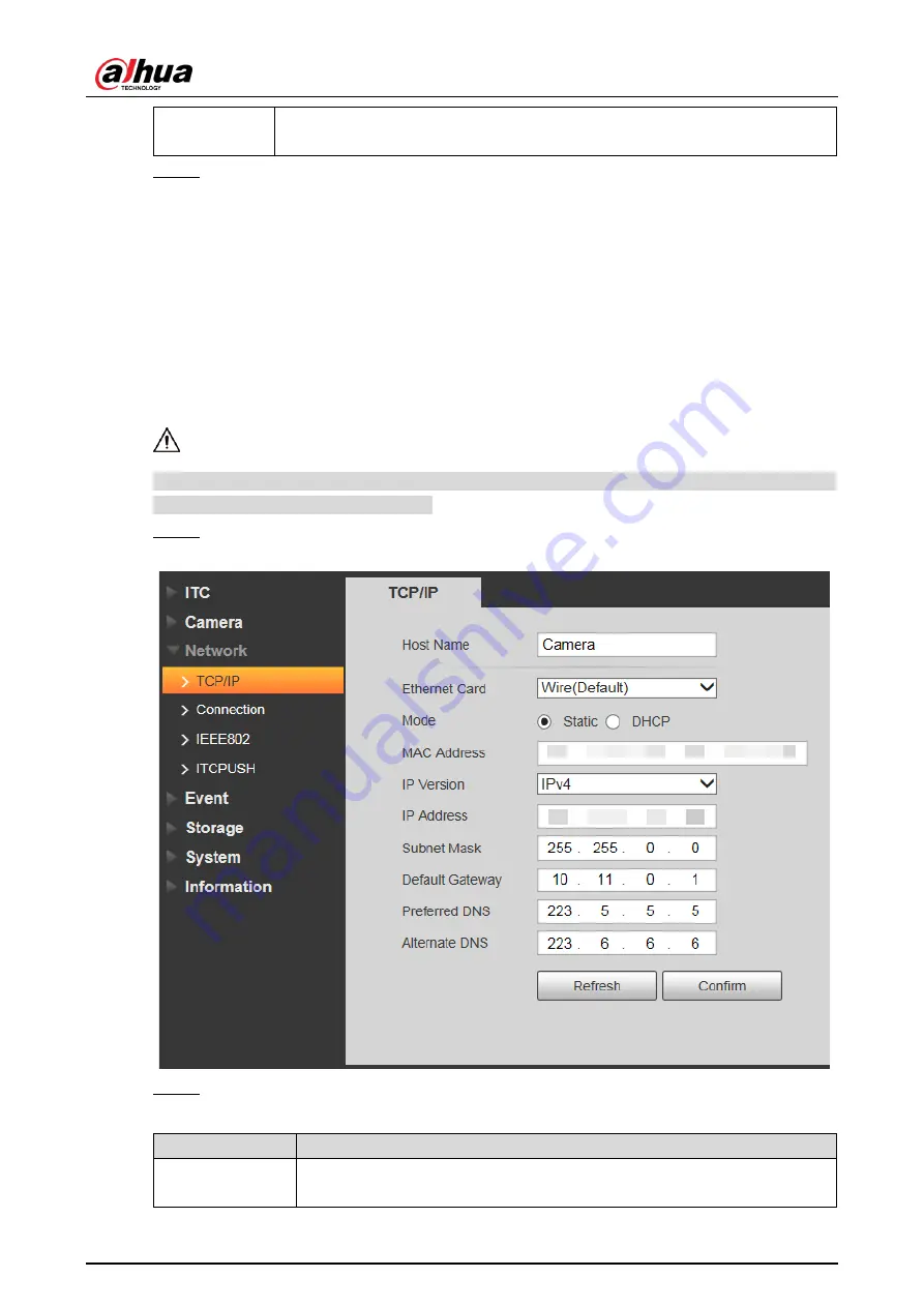
4.5.3.1 TCP/IP 

You need to configure the IP address of the Camera and DNS server. Make sure that it is 
connected to other devices in the network. 


Some models support dual network port. Do not set them in the same network segment; 
otherwise it might cause network error. 

Step 1  Select Setup > Network > TCP/IP. 

Figure 4-56 TCP/IP 


Step 2  Configure the parameters. 

Table 4-27 TCP/IP parameter description 

Parameter 

Description 

Host Name 

Enter a name for the host device. Maximum 15 characters are 
supported. 

Содержание DHI-ITC215-PW6M-IRLZF

Страница 1: ...Access ANPR Camera User s Manual V1 0 1 ZHEJIANG DAHUA VISION TECHNOLOGY CO LTD ...

Страница 2: ...C215 PW6M LZF B DHI ITC215 PW6M IRLZF O DHI ITC215 PW6M LZF O Safety Instructions The following categorized signal words with defined meaning might appear in the Manual Signal Words Meaning DANGER Indicates a high potential hazard which if not avoided will result in death or serious injury WARNING Indicates a medium or low potential hazard which if not avoided could result in slight or moderate in...

Страница 3: ...ll prevail All the designs and software are subject to change without prior written notice The product updates might cause some differences between the actual product and the Manual Please contact the customer service for the latest program and supplementary documentation There still might be deviation in technical data functions and operations description or errors in print If there is any doubt ...

Страница 4: ...CMOS Do not place the Camera in a damp or dusty environment extremely hot or cold temperatures or the locations with strong electromagnetic radiation or unstable lighting Keep the Camera away from any liquid to avoid damage to the internal components Keep the indoor device away from rain or damp to avoid fire or lightning Keep sound ventilation to avoid heat accumulation Transport use and store th...

Страница 5: ...ith your hands directly during installation or operation For removing dust grease or fingerprints wipe gently with moisten oil free cotton with diethyl or moisten soft cloth You can also air blower to remove dust Please strengthen the protection of network device data and personal information by adopting measures including but not limited to using strong password modifying password regularly upgra...

Страница 6: ...3 Spherical Bracket Installation 6 4 Web Configuration 9 4 1 Web Login 9 4 1 1 Recommended Configuration 9 4 1 2 Device Initialization 9 4 1 3 Login 12 4 1 4 Resetting Password 13 4 1 5 Web Functions 15 4 2 Guide 16 4 3 Live 19 4 3 1 Video Stream 19 4 3 2 Live View 19 4 3 3 Logged Plate Number 21 4 3 4 Plate Snapshot 21 4 3 5 System Functions 21 4 3 6 Functions of the Live Interface 21 4 3 7 Vehic...

Страница 7: ...User s Manual VI 4 5 5 Storage 63 4 5 6 System 67 4 5 7 Information 85 4 6 Alarm 87 4 7 Logout 88 5 FAQ 90 Appendix 1 Cybersecurity Recommendations 91 ...

Страница 8: ...user cannot exceed the permissions of its group 2 user levels Permission of opening barrier and blacklist alarm function Device configuration and permission management through Ethernet Storage Stores corresponding video data onto the central server according to the configuration such as alarm and timing settings Users can record through web according to their requirements The recorded video file w...

Страница 9: ...capture and encoding Supports picture watermark encryption to prevent pictures from being tampered The captured pictures can automatically record vehicle time location license plate vehicle color and more Peripheral Control Peripheral control Supports setting various peripheral control protocols and connection interfaces Connects to external devices such as vehicle detector signal detector and mor...

Страница 10: ...tructure 2 1 Long Range ANPR Camera Dimensions Figure 2 1 Camera dimensions mm inch Figure 2 2 Dimensions of camera with bracket mm inch 2 2 Short Range ANPR Camera Dimensions Figure 2 1 General camera dimensions mm inch ...

Страница 11: ...User s Manual 4 Figure 2 2 Dimensions of camera with bracket mm inch Figure 2 3 Dimensions of camera with spherical bracket mm inch 2 3 Structure 2 3 1 Entire Device Figure 2 4 Entire device structure ...

Страница 12: ...2 Illuminator 2 3 2 Rear Panel Figure 2 5 Rear panel structure Table 2 2 Description of rear panel structure No Description No Description 1 Debugging port 3 Hardware reset 2 TF card 2 4 Cable Connection Two cable connection methods are available and the actual product shall prevail Figure 2 6 Cable connection 1 ...

Страница 13: ...power Please be sure to supply power as instructed Device damage will occur if power is not supplied correctly 6 RS 485 RS 485 port Yellow RS 485_A1 Orange RS 485_B1 7 ALARM Alarm port Alarm output connecting to barrier and alarm output devices such as alarm light Brown ALARM_OUT1 Green ALARM_OUT_GND1 Red ALARM_OUT2 Black ALARM_OUT_GND2 Alarm input connecting to vehicle detector IR detector induct...

Страница 14: ...Red RS 485_A1 White Orange RS 485_B1 Yellow Green RS 485_A2 Yellow Black RS 485_B2 White Yellow RS 232_RXD White Brown RS 232_TXD White Black GND 4 ALARM Alarm port Alarm output connecting to barrier and alarm output devices such as alarm light Brown ALARM_NO1 Green ALARM_COM1 White Purple ALARM_NO2 Light Green ALARM_COM2 Red ALARM_NO3 Black ALARM_COM3 Alarm input connecting to vehicle detector IR...

Страница 15: ...e will occur if power is not supplied correctly 6 LAN Ethernet port Connects to standard Ethernet Supports PoE power supply 7 12V DC Power inputport Inputs 12V DC power Be sure to supply power as instructed Device damage will occur if power is not supplied correctly 8 BNC Video output port The Camera sends out video signal through this port ...

Страница 16: ...ew to fix the universal joint on the bracket Step 2 Use two 1 4 20 14UNC screws to fix the Camera on the universal joint See Figure 3 1 Figure 3 1 Universal joint installation Table 3 1 Components description No Description No Description 1 Camera 3 Universal joint 2 1 4 20 14UNC screw Step 3 Adjust the universal joint and the Camera to proper position Installation is completed ...

Страница 17: ...he No 1 and No 3 screws shown in Figure 3 2 Step 2 Insert all the camera cables into the bracket and then pull them out from the bracket tail Step 3 Use a M6 20 screw to fix the Camera and bracket The screw can be used to adjust the Camera upward and downward Step 4 Adjust the Camera to proper position and then tighten the screws 3 3 Spherical Bracket Installation Step 1 Insert the damping ring an...

Страница 18: ...ng Step 2 Cover the spherical bracket with bracket housing Step 3 Use three M6 20 socket head cap screws to fix the bracket housing to the Camera See Figure 3 4 For the illustration after installation see Figure 3 5 Figure 3 4 Fix the bracket housing ...

Страница 19: ...User s Manual 8 Figure 3 5 Installation completed ...

Страница 20: ... Browser Internet Explorer 9 11 Chrome 33 41 Firefox 49 4 1 2 Device Initialization The Camera is delivered uninitialized by default You need to initialize it and modify its password before further operations Before initialization make sure that both PC IP and device IP are in the same network segment otherwise it might fail to enter initialization interface Step 1 Set IP address subnet mask and g...

Страница 21: ...cial characters excluding and If you want to change your password again go to Setup System Account Account Step 5 Select the Email Address check box and then enter your email address recommended to set for resetting your password Step 6 Click Confirm Step 7 On the Online Upgrade interface click Confirm Figure 4 2 Config guide Step 8 Modify the default IP address subnet mask and default gateway and...

Страница 22: ...ername or password for 5 times consecutively See Figure 4 5 Figure 4 4 Login error Figure 4 5 Account locked Step 10Click Please click here to download and install the plug in in the video window The system automatically downloads webplugin exe and installs it according to prompt Before installing plug in make sure that the associated plug in option of active has been modified as Enable or Prompt ...

Страница 23: ...ng the steps below For first time login or logging in after restoring factory default Settings see 4 1 2 Device Initialization Step 1 Enter the IP address of the Camera in the browser address bar and press Enter Step 2 Enter your login username and password and then click Login The web interface is displayed A box pops up when the username or password is incorrect See Figure 4 8 If you enter inval...

Страница 24: ...email you need to reset password within 24 hours otherwise the security code will be invalid One device can generate security code up to 10 times in one day so the Camera can be reset up to 10 times in one day Email address must be filled in during device initialization otherwise it will fail to send you the security code and you will not be able to reset your password Email address of admin can b...

Страница 25: ...pt click No and continue to run the script Figure 4 11 Reset password 1 Step 4 Scan the QR code according to the interface prompt and send the scanning result to designated email and acquire security code Scan the actual QR code Do not scan the QR code in this manual Step 5 Enter received security code in the text box of Security code Step 6 Click Next ...

Страница 26: ...eb Functions This section mainly introduces the following 6 functions on the web interface Figure 4 13 Tab Table 4 2 Tab function description Tab Function Guide Quick configuration of plate pixel recognition region and more Live View and record live video and image adjust video and image window set client image parameter and so on Query Search for different types of pictures and videos and configu...

Страница 27: ...alue which is the latest saved Click the button after the parameter configuration is completed and then it makes the current settings valid 4 2 Guide On the Guide interface you can configure capture scenarios and get assistance with setting installation scenario You can click at the upper right corner of Guide interface to exit Step 1 Click the Guide tab Figure 4 14 Confirmation Step 2 Confirm Sof...

Страница 28: ...k Snapshot to take a snapshot of the plate Snapshot becomes Resume 3 Drag the yellow plate pixel box to the position of the plate 4 Click Zoom Zoom in the picture selected by the plate pixel box It can realize 2x or 4x zoom rate 5 Adjust the position of plate pixel box and make it the optimal plate size See Figure 4 16 If the plate within the yellow box is larger than the optimal plate size in the...

Страница 29: ... 4 18 Recognition Step 4 Configure recognition area The configuration example on the right of video interface can be used as a reference 1 Click Iden Area identification area Click and draw 4 lines on the video interface and the recognition area is formed 2 Click Snap Line Draw snap line by dragging mouse on the area The snap line must cross the area ...

Страница 30: ...hot 4 Plate snapshot 8 Event list 4 3 1 Video Stream Main Stream Make sure that the Camera can record video and carry out network surveillance when the network is normal You can configure main stream resolution within the supported range of the Camera Sub Stream Replaces main stream to make network surveillance and reduce the network bandwidth possession when network bandwidth is insufficient Prot...

Страница 31: ... see Click it and the image is 100 displayed meanwhile the button turns to Click to switch back to original size Click it to enable smart track detection Number plate vehicle bounding box and other smart tracking information will be displayed in the video image Click it and the window is displayed in full screen double click or right click to exit full screen Table 4 5 Image adjustment Icon Name D...

Страница 32: ...ed Plate Number Displays the plate number recognized by the Camera in real time when a vehicle passes 4 3 4 Plate Snapshot Displays the snapshot of license plate when a vehicle passes 4 3 5 System Functions Click the icons to set system functions which include playback video recording and snapshot query intelligent rules setting alarm event setting and system logout See more details in the followi...

Страница 33: ...a in the video window and then the area will be zoomed in In any area of the video window click or right click to exit Video Recording Click it to start recording Click again to stop recording You can set the storage path of video recordings from Setup Storage Destination Save Path Config LPR You can draw the area of plate detection adjust camera s focal length and set local character Click and th...

Страница 34: ...uide are displayed in the video interface Table 4 8 Line parameters description Parameter Description Iden Area Click it and draw the area range which needs to be detected The recognition area line is displayed as red box Snap Line Draw the detection line which triggers video capture it is as functional as the line in traffic It will trigger and take snapshot when the vehicle crosses the detection...

Страница 35: ...of the Camera Step 6 Set Spotlight Brightness Drag the block and set brightness of flashing light according to actual requirement Step 7 Click Confirm 4 3 7 Vehicle Snapshot Select ANPR Receive and then snapshots will be displayed when vehicles pass 4 3 8 Event List Select ANPR Receive and the event information will be displayed including No event types capture time lanes plates vehicle color spee...

Страница 36: ...arameter Description Begin Time Set the start time of picture query End Time Set the end time of picture query Event Type Search for all pictures or search for pictures which conform to requirements according to filtering condition based on violation type Vehicle Sign Take vehicle sign as query condition then it can select one or all Plate Seelct the Plate check box take plate feature as query con...

Страница 37: ...ialog box The system starts to download the pictures to local PC Click Open or double click the picture if you need to preview the picture If several picture files are selected at the same time click Open to open all the pictures 4 4 1 2 Download Picture Attribute In this section you can set the picture download time and mode Confirm picture name according to Help Step 1 Select Query Picture Query...

Страница 38: ...w the naming rule of downloaded pictures Step 3 Click Confirm 4 4 1 3 PC Picture The section introduces the way of checking whether the watermark of PC picture is tampered Step 1 Select Query Picture Query PC Picture Figure 4 25 PC picture Step 2 Click Open Local and select the folder where the verified picture is located Step 3 Select the picture which needs to be verified Step 4 Click Water Veri...

Страница 39: ...lick it to pause Stop Click it to stop playing video Slow down Play Click it to slow down video playing Speed up Play Click it to speed up video playing Play by Frame Click it to skip to the next frame 4 4 2 2 Watermark In this section you can verify whether the watermark of local record is tampered Go to Setup Camera Video Video and check Watermark Settings if you want to enable the function and ...

Страница 40: ...layed after verification is finished 4 4 3 Plate Query Search for the vehicle record within the defined period and according to the defined direction It supports max 10 000 records or 1 024 records respectively when the camera is installed with or without TF card If the passing vehicle records are unreadable in Excel after being imported change them into UTF 8 encoding document in txt and then the...

Страница 41: ...al parameters such as ITC camera network event storage system and system information 4 5 1 ITC You can set intelligent parameters of the Camera 4 5 1 1 Detection 4 5 1 1 1 Snapshot You can set snapshot rule of the Camera Step 1 Select Setup ITC Detection Snapshot Figure 4 29 Snapshot Step 2 Configure the parameters Table 4 12 Description of capture parameters Parameter Description Work Mode Coil U...

Страница 42: ...ation and loop IO snapshot configuration Select Setup ITC Detection RS485 IO the RS485 IO interface is displayed Start RS 485 Port Step 1 Select Start RS485 Port but not Start Coil IO Figure 4 30 RS485 IO start RS485 port Step 2 Select Protocol and set protocol type according to the number of com port Select CarDetect from Protocol 1 Set the baud rate of the protocol 2 Select scheme Single_in1 sna...

Страница 43: ...tart Coil IO but not select Start RS485 Port Figure 4 31 RS485 IO Start Coil IO Step 2 Configure the parameters Table 4 13 Coil IO parameters description Parameter Description Trigger Mode Config IO Only Coil IO can be selected Coil 1 Set the coil trigger mode No trigger No capture is triggered Rise Edge Capture is triggered when the vehicle enters coil Drop Edge Capture is triggered when the vehi...

Страница 44: ...napshot configuration of coil IO and RS 485 port configuration See Figure 4 32 Figure 4 32 RS485 IO Start RS485 and Coil IO 4 5 1 1 3 Com Push Push the snapshot and data information mode to server according to actual requirement Set Comm Push as the Protocol from RS485 IO and set the Baud Rate otherwise the Comm Push function will not be available Step 1 Select Setup ITC Detection Comm Push Figure...

Страница 45: ...Tag Tail Com port protocol tail the standard is 4 bit it can only input hexadecimal character Encode mode It is the encoding mode of Com port push content Check mode verification mode of com port protocol Up Move Click it select the corresponding option and move up Down Move Click it select the corresponding option and move down 4 5 1 2 Intelligent 4 5 1 2 1 Recognition You can set vehicle recogni...

Страница 46: ...e and the optimal width of the location Make sure that the location and size of plate is in accordance with that of the yellow line box Repeat Plate CheckTime One plate can only trigger one ANPR event within the period Car Detect Sensitivity Set the sensitivity of vehicle detection The higher the value the more sensitive the detection Step 3 Click Confirm 4 5 1 2 2 Advance Configuration In this se...

Страница 47: ... higher the confidence level is the more limited conditions there will be and correspondingly the plate is harder to be recognized and false capture rate becomes lower as well Advanced Options Enters customized algorithm expression and realize customized special function Step 3 Click Confirm 4 5 1 3 OSD Configuration 4 5 1 3 1 Video OSD Set OSD information of video channel Step 1 Select Setup ITC ...

Страница 48: ...etup ITC OSD Config Snap OSD Figure 4 37 Snap OSD Step 2 Move the title box to displayed location or manually enter coordinate value into the X Y box in the lower right corner of the interface Step 3 Select Black Edge Location and then you can set the position of the OSD black strip You can select from Above Below and None Step 4 Set font size of OSD information You can set font color of picture O...

Страница 49: ...on status is displayed as except line feed Click to modify the prefix suffix content and separator of corresponding OSD option Delete Click it and all the selected OSD information status is displayed as click to delete corresponding OSD option Clear Delete all the OSD information Line Feed After selecting some OSD information click Line Feed and OSD information will be displayed on the picture Ste...

Страница 50: ... ITC Detection RS485 IO then it can detect whether the associated information and status of vehicle detector is normal Select Setup ITC Extra Device Extra Device Status The Extra Device Status interface is displayed Figure 4 40 Extra device status 4 5 1 5 2 Spotlight This section provides guidance on configuring light array and output mode of flashing light Step 1 Select Setup ITC Extra Device Spo...

Страница 51: ...u can automatically turn on or turn off spotlight according to time or brightness Time Set the period during which the spotlight is enabled Up to 6 periods can be set for each day Brightness Set brightness default value Spotlight is enabled when environmental brightness is lower than the default value and the spotlight is disabled when it is higher than default value Auto Mode setting is only appl...

Страница 52: ...acter or after the last character of the plate Fault Tolerant Character Set the fault tolerance value 0 1 or 2 and plate number will be matched successfully when 0 1 or 2 characters different from the recorded plate number are detected Character Match Limitation Click to add the fuzzy match condition For example if o is deteced by the Camera the character will be automatically recognized as 0 as s...

Страница 53: ...ate number Click Yes to complete modification after modification is finished Delete single plate number Click of the corresponding plate number searched and delete it from the allow list Delete plate number in batches click Clear All and click Confirm in the dialog box to delete all the allow list information Adding vehicles to allow list one by one 1 Click Add Figure 4 45 Add 2 Enter complete pla...

Страница 54: ...x 2 Check Open encrypt or Close do not encrypt as needed and then click Confirm The export file download dialog box pops up 3 Select the path of storing files Click Save and export white list to local in csv format which can be opened in Excel Importing vehicles to white list in batches 1 Click Template to download the template or open the csv file you exported fill in the allow list data which ne...

Страница 55: ...ar to those of the allow list See 4 5 1 6 2 White List Search for more details 4 5 1 6 4 Barrier Control You can set the barrier control mode and configure information of opening and closing barrier Step 1 Select Setup ITC BW List Barrier Control Figure 4 47 Barrier control Step 2 Configure the parameters ...

Страница 56: ...Order Server Platform issues command and output open barrier signal Server IP After enabling open barrier command and configuring IP if the device is offline barrier will be opened by white list function automatically Open Test Click the button and manually trigger outputting signal of opening barrier Close Test Click the button and manually trigger outputting signal of closing barrier Open Config...

Страница 57: ...ge brightness contrast hue saturation and ICR switch Step 1 Select Setup Camera Attribute General Figure 4 50 General Settings Step 2 Configure the parameters Table 4 21 General parameters description Parameter Description Brightness Adjust the overall image brightness Change the value when the image is too bright or too dark The bright and dark areas will have equal changes The image becomes blur...

Страница 58: ...value is the more flamboyant the image becomes Gamma Adjust the image hue For example change red into blue The default value is made by the light sensor and normally it doesn t have to be adjusted The recommended value is from 40 to 60 and the range is from 0 to 100 It is 50 by default The threshold is used to adjust image hue and ot will not influence image overall brightness ICR Switch Auto Set ...

Страница 59: ... Dawn Dusk Daytime and Night Sharpness You can set the sharpness of corresponding scene The higher the value the clearer the image But there will be noise if sharpness is too high WDR Select On to enable WDR wide dynamic range which helps provide clear video images in bright and dark light Exposure Iris Type Displays the detected iris type Iris Adjust Mode Select the way of adjusting exposure mode...

Страница 60: ...ription Plate Light When selecting Enable you can turn ON or OFF backlight and frontlight according to scene requirement and then improve the backlight image brightness Backlight Frontlight Measure Mode Global Measure Measure the brightness of the whole image area and intelligently adjust the overall image brightness Partial Measure Measure the brightness of sensitive area and intelligently adjust...

Страница 61: ...e Include VBR and CBR Image quality can be set only in VBR mode while it cannot be set in CBR mode Bit Rate The value is the upper limit of the stream in VBR mode while it is fixed in CBR mode I Frame Interval P frame quantity between two I frames it is max 150 The system default is set twice as big as frame rate Watermark Settings You can view if the video is tampered through verifying watermark ...

Страница 62: ...e The value is the upper limit of the stream in VBR mode while it is fixed in CBR mode I Frame Interval P frame quantity between two I frames it is max 150 The system default is set twice as big as frame rate Step 3 Click Confirm 4 5 2 2 2 Snapshot You can set the picture stream including resolution quality or picture size Step 1 Select Setup Camera Video Snapshot Figure 4 54 Snapshot Step 2 Confi...

Страница 63: ... with configured quality It supports max 3 regions at the same time The image quality is displayed by level Worst Worse Bad Good Better or Best Click Remove All and delete all the area boxes Select one box and then click delete or right click to delete it Step 1 Select Setup Camera Video Interest Area Figure 4 55 Interest area Step 2 Configure parameters See Table 4 26 Table 4 26 Interest area par...

Страница 64: ...o configure the IP address of the Camera and DNS server Make sure that it is connected to other devices in the network Some models support dual network port Do not set them in the same network segment otherwise it might cause network error Step 1 Select Setup Network TCP IP Figure 4 56 TCP IP Step 2 Configure the parameters Table 4 27 TCP IP parameter description Parameter Description Host Name En...

Страница 65: ...teway Corresponding gateway of device IP address Preferred DNS IP address of DNS server Alternate DNS Alternate IP address of DNS server Step 3 Click Confirm 4 5 3 2 Connection 4 5 3 2 1 Port You can set the connected port information it can access device through different protocols or config tool Step 1 Select Setup Network Connection Port Figure 4 57 Port Step 2 Configure each port value of the ...

Страница 66: ...video products of different manufacturers interworking ONVIF login authentication is enabled by default Step 1 Select Setup Network Connection ONVIF Figure 4 58 ONVIF Step 2 Select the Turn on check box Step 3 Click Confirm 4 5 3 3 SMTP Email Configure the email and when alarms or abnormal events are triggered an email will be sent to the recipient server through SMTP server The recipient can log ...

Страница 67: ...cters in English letters and numbers Mail Receiver Email address of the receiver Supports 3 addresses at most Attachment Select the check box to support attachment in the email Interval The interval of sending emails Health Mail The system sends test mail to check whether the connection succeeds Select the Health Mail check box and configure the Update Period and then the system sends test mails a...

Страница 68: ... client and the server must be assigned a digital certificate signed by a CA Certificate Authority that they both trust CA Certicate Select the CA Certificate check box and then click Browse to import the CA Certificate to verify whether the switch is valid PEAP Username For PEAP method user authentication is performed by using password based credentials username and password Password EAP TLS Clie...

Страница 69: ...ttp Time Out s Timeout of Http push message Keep Alive Time s You can set Keep Alive Time Character Encoding Encode mode of push content which includes UTF8 and GB2312 Upload List Type Select the type of list that you want to upload Push Picture Config Select the pushed picture type and it includes Original Image Plate Picture and Vehicle Body Picture Upload Info Config Select the information that...

Страница 70: ...up Figure 4 63 Period 2 Click Setup corresponding to the day you need to configure time period 3 Select the period you need to enable and enter start time and end time of corresponding period 4 If you need to apply this period setting to any other day select the check box of the corresponding days 5 Click Confirm to save the settings You can repeat these steps to apply the Settings to other days S...

Страница 71: ...s alarm when alarm occurs Step 5 Click Confirm 4 5 4 1 2 Relay out In this section you can trigger one alarm output signal Step 1 Select Setup Event Alarm Relay out Figure 4 64 Relay out Step 2 Click 1 2 or 3 and set 1 channel of alarm channel Step 3 Set alarm output Click Trigger to output relay out signal Click Refresh to refresh alarm output status 4 5 4 2 Abnormality This section provides guid...

Страница 72: ...User s Manual 61 Figure 4 65 No storage card Figure 4 66 Storage error Figure 4 67 Not enough storage space Figure 4 68 Camera offline ...

Страница 73: ... 72 Vehicle in the black list Step 2 Configure the parameters of each event as needed Table 4 33 Abnormality parameters Parameter Description Enable Check to enable corresponding abnormality event Relay out Check to enable the corresponding alarm output of abnormality event and select the corresponding port ...

Страница 74: ...gure the number of login error allowed The range is 3 10 times Send Email The system sends an email to the defined email address when an alarm is triggered To set the email address go to Setup Network SMTP Email Step 3 Click Confirm 4 5 5 Storage This section provides guidance on setting associated information of storage and record control 4 5 5 1 Point Set the storage path of snapshot Step 1 Sele...

Страница 75: ...mation of the card Click Hot Swap and then you can pull out the SD card Click Format and then you can format the SD card Figure 4 74 Local Step 2 Click Confirm 4 5 5 3 FTP FTP function can be enabled only when it is selected as destination path When the network does not work you can save all the files to the internal SD card for emergency You can set picture name and storage path Click Help to vie...

Страница 76: ...g rule Enable Enable FTP server storage Protocol SFTP Recommended Secure File Transfer Protocol a network protocol allows file access and transfer over a secure data stream FTP File Transfer Protocol a network protocol implemented to exchange files over a TCP IP network Anonymous user access is also available through an FTP server Server IP The IP address of FTP server Encode Mode Refers to the en...

Страница 77: ...on will be displayed Then you can configure Begin Time and End Time and choose the server to upload Type Select connection type with platform server IP Connect to platform server through IP address MAC Connect to platform service through MAC address Server Select server which includes Server1 and Server2 Server IP When the type is selected as IP then it has to fill in the server s IP address When ...

Страница 78: ...the root path of record and snapshot as needed Step 4 Click Confirm 4 5 6 System You can configure general information adding user restoring default settings and configuring import export file 4 5 6 1 General 4 5 6 1 1 General This section provides guidance on configuring device SN language and video standard Step 1 Select Setup System General Setup General Setup ...

Страница 79: ...rts English Video Standard PAL Phase Alternating Line Currently most countries around the world including most countries in Europe Africa Australia and China adopt this standard NTSC National Television System Committee The main countries which adopt this standard include America Canada and Japan Machine Group The company group information of the Camera Machine Address Set the location information...

Страница 80: ... becomes valid immediately after setting Sync PC Sync the time of the Camera with the time on PC DST Enable the function and then set begin time and end time of DST Set according to date or week NTP Setting Select to enable the function of network time synchronization Server Time server address Port Port number of time server Time Zone The time zone where the Camera is located Interval The sync in...

Страница 81: ...me The user with Account control authority can also modify the password of other users It is recommended to give fewer authorities to normal users than premium users in order to make user management convenient Cannot delete the user in login status You can add delete or modify user Step 1 Select Setup System Account Account Username Figure 4 80 Username Step 2 Click Add User ...

Страница 82: ...from 8 characters to 32 nonblank characters and contains at least two categories from upper cases lower cases numbers and special characters excluding and Follow the password security prompt to set a high security level password Password should be the same as Confirm Password Confirm Password Group Name Select the group that new users belong to Each group has different authorities Memo Remarks on ...

Страница 83: ... and email address User Group You have two groups named admin and user by default you can add new group delete added group or modify group authority and memo Step 1 Select Setup System Account Account Group Name The system supports max 8 user groups and the default initialization user groups are admin and user You can modify and delete the added user group but not the initialization user group Fig...

Страница 84: ...oup list After adding group click to modify group memo or authorities click to delete the added group admin group and user group can not be deleted Click in the row of admin group or user group to modify group memo 4 5 6 2 2 ONVIF User You can add delete modify Onvif Open Network Video Interface Forum on the user management interface Step 1 Select Setup System Account Onvif User Figure 4 84 Onvif ...

Страница 85: ...ord should be in accordance with the confirm password Confirm Password Group Name The group that users belong to Each group has different authorities Step 4 Click Save The newly added user is displayed in the user list After adding user click to modify user password group memo and authorities click to delete the added user admin user cannot be deleted Click in the admin row to modify user name and...

Страница 86: ...transmission Make sure that the device or software supports video decryption function Private Protocol Authentication Mode Keep the recommended Security Mode Step 3 Click Confirm 4 5 6 3 2 HTTPS For first time use of HTTPS or after changing device IP address you need to create server certificate and install root certificate After creating server certificate and installing root certificate if it re...

Страница 87: ... 3 Enter the required information such as region IP or domain name and then click Create The entered IP or Domain name must be the same as the IP or domain name of the Camera 4 Click Install and then click Download to download root certificate The system pops up Save As dialog box select storage path and then click Save ...

Страница 88: ...User s Manual 77 Figure 4 89 Download root certificate 5 Double click the RootCert cer icon Figure 4 90 Certificate information 6 Click Install Certificate ...

Страница 89: ... Certificate import wizard 7 Click Next The Certificate Store interface is displayed You can select automatically select the certificate store based on the type of certificate or place all certificates in custom certificate store ...

Страница 90: ...User s Manual 79 Figure 4 92 Certificate store 8 Click Next Figure 4 93 Completing certificate import wizard 9 Click Finish ...

Страница 91: ...low the steps below 1 Select Setup System Safety HTTPS 2 Select Enable HTTPS and Enable TLSv1 0 3 Click Browse to upload the signed certificate and certificate key and then click Upload 4 To install the root certificate see operation steps from 4 to 10 in Create Certificate Step 2 Select Enable HTTPS and click Confirm The Reboot interface is displayed Configuration takes effect Wait until the Came...

Страница 92: ...played xx xx xx xx is your device IP address or domain name Step 2 Enter the username and password to log in to the Camera The browser will prompt certificate error if certificate is not installed See Figure 4 97 Figure 4 97 Certificate error 4 5 6 3 3 Firewall Set the security rules to protect the safety of your camera system Step 1 Select Setup System Safety Firewall ...

Страница 93: ...p 3 Select Enable to enable the rule type that you selected Step 4 Click Confirm 4 5 6 4 Default Settings You can restore the device to default Settings or factory defaults Default Restore your settings to default value In this case network IP address information of the Camera will not restore to default settings Factory Default Restore the system to factory default settings In this case the Camer...

Страница 94: ...Import Export Figure 4 100 Import Export Step 2 Click Import or Export Import Import the local system configuration file to the system Export Export associated configuration to local and save as file whose suffix is backup Step 3 Select the imported file path or exported folder Step 4 Click Open or Save and view import and export result on the web interface 4 5 6 6 Automatic Maintenance Users can ...

Страница 95: ...ore the time Manual Reboot Manually restart the Camera Step 3 Click Confirm 4 5 6 7 System Upgrade Upgrade system of the Camera to keep the camera functions always working You can upgrade the system by using upgrade file or through online upgrade Upgrading the wrong program might result in the Camera not working properly During upgrading make sure that the Camera is not disconnected from power and...

Страница 96: ...You can view the version information of the Camera Select Setup Information Version and then the Version interface is displayed Versions of different devices might vary and the actual web interface shall prevail Algorithm recognition is available when algorithm is authorized when the icon is displayed in green If algorithm is not authorized the Camera will not be able to recognize vehicle series m...

Страница 97: ... Time and End Time and then select log type Step 3 Click Search and it can start searching according to requirement Step 4 View back up and clear the searching results Backup Backup the searched system log information to local The backup file is in txt format 4 5 7 2 2 Remote log You can save your important logs to log server This helps provide important clues to the source of security incidents L...

Страница 98: ...firm to restore to default Settings 4 5 7 3 Online User You can view the information of all the online users on this interface Select Setup Information Online User and the Online User interface is displayed Figure 4 106 Online user Click Refresh to view the latest status 4 6 Alarm Click the Alarm tab and then the Alarm interface is displayed You can select alarm type operation and tone view the al...

Страница 99: ...e is no storage card Black List It triggers alarm when the blacklist vehicle appears Illegal Access It triggers alarm when the times of login password error reach the max value Security Exception It triggers alarm when there is security exception Operation Listen Alarm The web will prompt user when device alarm occurs Alarm Tone Play Alarm Tone It generates alarm prompt tone when alarm occurs Alar...

Страница 100: ...User s Manual 89 Figure 4 108 Login again ...

Страница 101: ...rage media of pre set recording It may damage the TF card duration TF card cannot be used as storage media When the TF card hibernates or its capacity is null format the card through web first Network upgrade failed Check whether the right upgrade program such as version compatibility is used Recommended TF card It is recommended to use TF card of 16 GB or above This helps avoid data loss arising ...

Страница 102: ...nable the auto check for updates function to obtain timely information of firmware updates released by the manufacturer We suggest that you download and use the latest version of client software Nice to have recommendations to improve your equipment network security 1 Physical Protection We suggest that you perform physical protection to equipment especially storage devices For example place the e...

Страница 103: ... services SNMP Choose SNMP v3 and set up strong encryption passwords and authentication passwords SMTP Choose TLS to access mailbox server FTP Choose SFTP and set up strong passwords AP hotspot Choose WPA2 PSK encryption mode and set up strong passwords 11 Audio and Video Encrypted Transmission If your audio and video data contents are very important or sensitive we recommend that you use encrypte...

Страница 104: ...ested to use VLAN network GAP and other technologies to partition the network so as to achieve the network isolation effect Establish the 802 1x access authentication system to reduce the risk of unauthorized access to private networks It is recommended that you enable your device s firewall or blacklist and whitelist feature to reduce the risk that your device might be attacked ...

Страница 105: ......

Отзывы: