User’s Manual
18
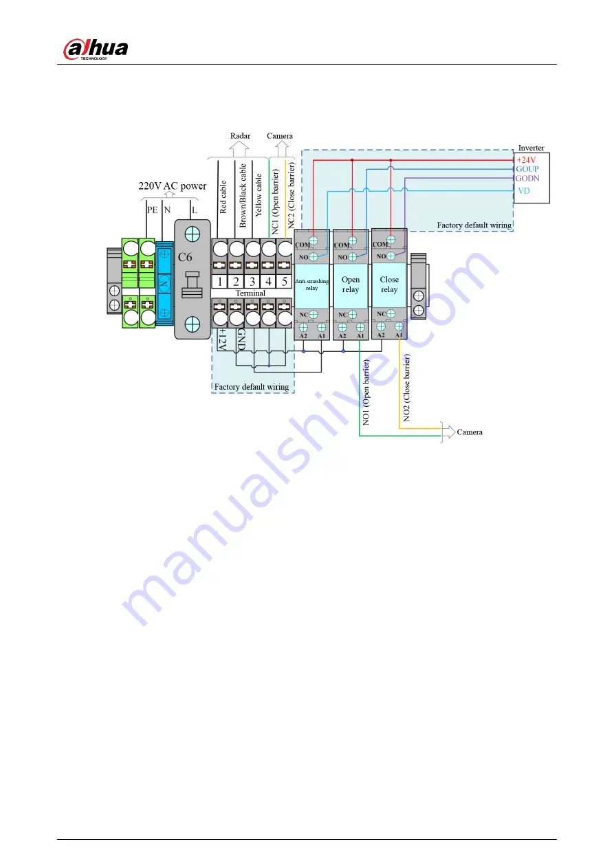
3.4.2 Wiring Instructions
Wiring diagram
Figure 3-13
Connect to power:
PE: Connect to earth wire.
N: Connect to neutral wire.
L: Connect to live wire.
Connect to radar:
+12V: Connect to red cable of radar.
GND: Connect to brown/black cable of radar.
A1 (anti-smashing relay): Connect to yellow cable of radar through port 3 (terminal).
Connect to camera:
Open barrier: Connect A1 (open relay) to NO1 (camera), and connect GND (terminal)
to NC1 (camera) through port 4 (terminal). See green lines in the figure above.
Close barrier: Generally you do not need to connect cables for controlling barrier
closing signals. If you want to, connect A1 (close relay) to NO2 (camera), and connect
GND (terminal) to NC2 (camera) through port 5 (terminal). See yellow lines in the
figure above.
Connect to IR sensor for anti-smashing:
To connect the IR sensor for anti-smashing, connect NO (close relay) to GODN (inverter),
and connect A1 (close relay) and GND (through port 5 of the terminal) to anti-smashing
terminals of the IR sensor.


