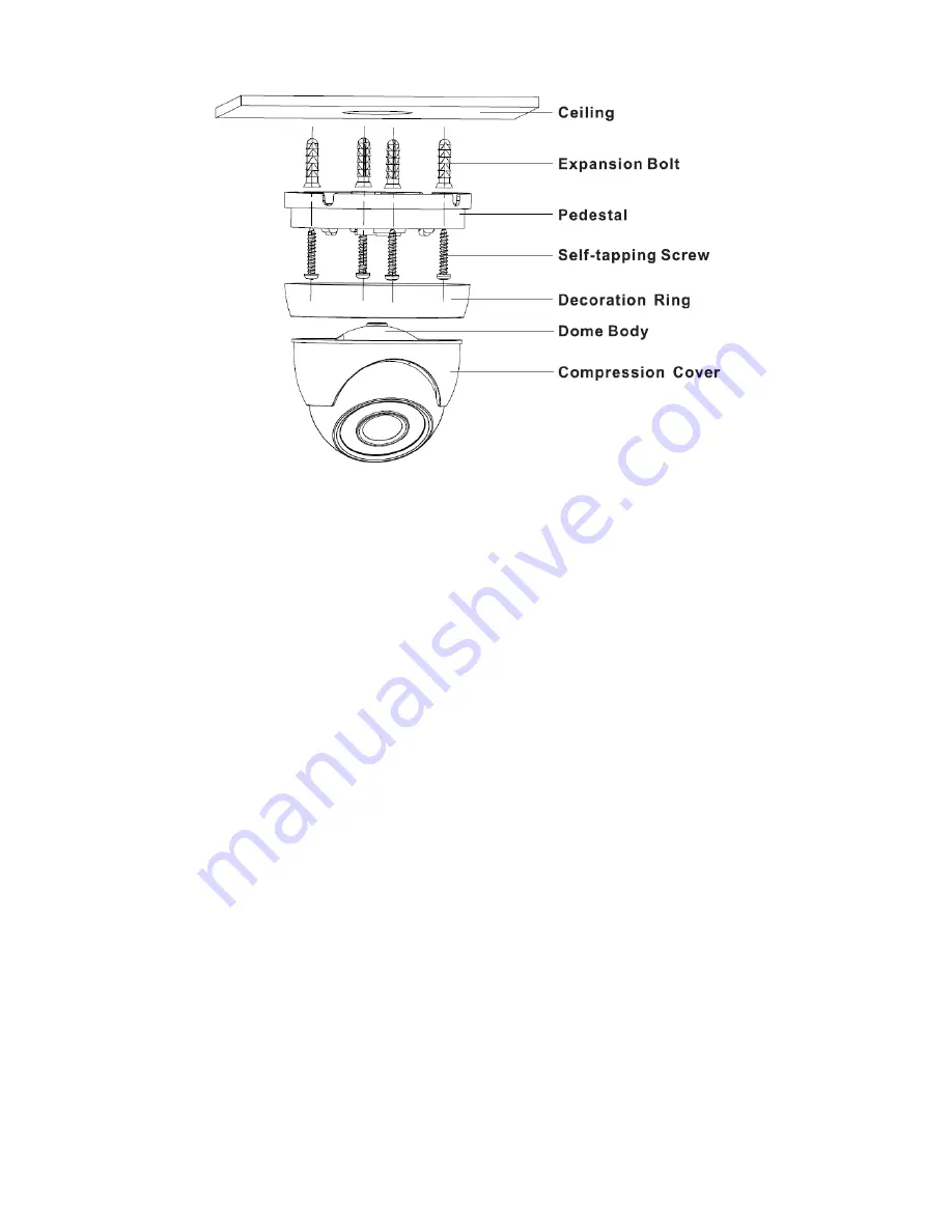
Dahua A Скачать руководство пользователя страница 12


Figure 3-4 

Step 1  

Hold the decoration ring tightly and unscrew the pedestal anticlockwise.  

Step 2 

Confirm the installation location and dig holes on the installation surface.  

Step 3 

Use tools to insert expansion bolts into the installation holes and fix them firmly. 

Step 4  

Adjust pedestal location (if it is side cable outlet, then pull the cable through the side outlet 

cable slot). Align the bolt fixing holes of the device pedestal with the expansion bolt fixing holes 

of the installation surface; insert the self-tapping screws into the expansion bolts and fasten 

them firmly to fix the pedestal on the installation surface (if it is top outlet, pull the cable 

through the outlet hole on the installation surface after the pedestal is fixed firmly). 

Step 5  

Rotate the decoration ring and fix it slightly, rotate the compression cover and dome body to a 

proper monitoring location; finally rotate the decoration ring firmly.  


So far the device installation and cable connection are completed; you can check the image 

via back-end coding device.  


Model D 

Содержание A

Страница 1: ...HDCVI Camera User s Manual Version 1 0 0...

Страница 2: ...l Introduction 1 1 1 Overview 1 1 2 Features 1 2 Device Framework 2 3 Installation 5 Model A 5 Model B1 and B2 6 Model C 7 Model D 8 Model E 9 Model F 10 4 Menu 12 4 1 HCVR Settings 12 4 2 Menu Operat...

Страница 3: ...device 2 Environment Please don t aim the device at strong light such as lighting sunlight and so on to focus Please transport use and store the device within the range of allowed humidity and temper...

Страница 4: ...l is just for reference The manual will be regularly upgraded according to the product update the upgraded content will be added in the manual without prior announcement Please contact the supplier or...

Страница 5: ...ries support RG59 coaxial cable transmission without any loss The distance is over 500m PoC power supply supports transmission distance up to 400m for 1080P and 300m for 4MP via RG59 Support HDCVI HD...

Страница 6: ...2 2 Device Framework See Figure 2 1 for the dimension of model A Figure 2 1 See Figure 2 2 and Figure 2 3 for the dimension of model B1 and model B2 Figure 2 2 Figure 2 3...

Страница 7: ...Figure 2 4 for the dimension of model C Figure 2 4 See Figure 2 5 for the dimension of model D Figure 2 5 See Figure 2 6 for the dimension of model E Figure 2 6 See Figure 2 7 for the dimension of mo...

Страница 8: ...r PoC models the port can realize both power input via coax and video output at the same time during PoC power supply PoC can be supported only in the HDCVI video output mode Warning Any device is not...

Страница 9: ...s of the device pedestal with the expansion bolt fixing holes of the installation surface insert the self tapping screws into the expansion bolts and fasten them firmly to fix the pedestal on the inst...

Страница 10: ...delivered from factory it has to adjust clockwise when adjusting Zoom end for the first time 2 It has to twist slowly when adjusting Focus end you need to check the image definition when twisting Foc...

Страница 11: ...fixing holes of the installation surface insert the self tapping screws into the expansion bolts and fasten them firmly to fix the pedestal on the installation surface if it is top outlet pull the ca...

Страница 12: ...e pedestal with the expansion bolt fixing holes of the installation surface insert the self tapping screws into the expansion bolts and fasten them firmly to fix the pedestal on the installation surfa...

Страница 13: ...ust pedestal location if it is side cable outlet then pull the cable through the side outlet cable slot Align the bolt fixing holes of the device pedestal with the expansion bolt fixing holes of the i...

Страница 14: ...t fixing holes of the installation surface insert the self tapping screws into the expansion bolts and fasten them firmly to fix the pedestal on the installation surface if it is top outlet pull the c...

Страница 15: ...osure on the device pedestal Step 3 Install the rotation ring after the enclosure is fixed on the pedestal together with the dome body make sure the location of pedestal cable exit hole is in accordan...

Страница 16: ...u Setting System PTZ you need to select the channel number for access and set control mode as HDCVI and the protocol as HD CVI Click Save button to save current setup See Figure 4 1 Figure 4 1 4 2 Men...

Страница 17: ...tton functions Button Function Open menu Select menu item Select menu value Sheet 4 1 4 3 Set Audio Coax From Main Menu Setting Camera Encode Encode you need to set Audio Format as G711a and the Audio...

Страница 18: ...output Note This manual is for reference only Slight difference may be found in the user interface All the designs and software here are subject to change without prior written notice All trademarks a...

Отзывы: