background image

  System  Configurations 

49 

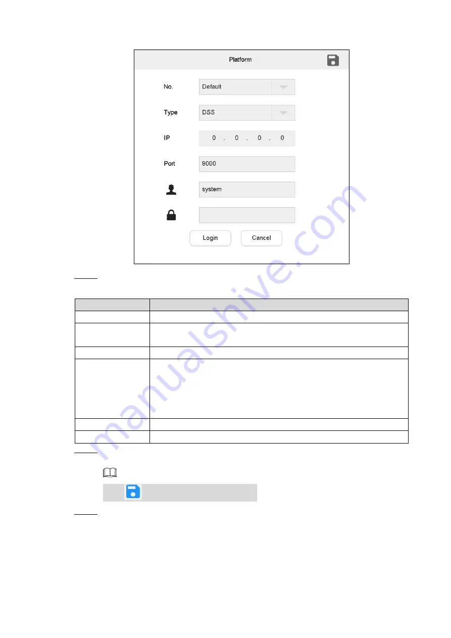
 Connect keyboard operation platform 

Figure 4-43


  Set parameters. Refer to Table 4-6. 

Step 2

Table 4-6 Platform parameter description 

Parameter 

Description   

No. 

Customize platform number. 

Type 


Select  platform  type,  including  DSS  (the  old  version  before 

DSS-PRO), DSS-PRO, DSS-C9100 and DSS- Express. 

IP 

Enter IP address of platform. 

Port 

Set port number. 


Regarding DSS platform, default port number is 9000. 


Regarding DSS-PRO and DSS-Express platform, default port number 

is 80. 


Regarding DSS-C9100 platform, default port number is 8314. 

Username 

Enter username to log in to the platform. 

Password 

Enter password to log in to the platform. 

  Click 

Login

Step 3

The 

Login

 interface is displayed. 


Click 

  to save the present information. 

  Select platform. See Figure 4-44. 

Step 4

Содержание 5000 Series

Страница 1: ...Network Keyboard 5000 Series Quick Start Guide V2 0 0 ...

Страница 2: ...ning DANGER Indicates a high potential hazard which if not avoided will result in death or serious injury WARNING Indicates a medium or low potential hazard which if not avoided could result in slight or moderate injury CAUTION Indicates a potential risk which if not avoided could result in property damage data loss lower performance or unpredictable result TIPS Provides methods to help you solve ...

Страница 3: ...hall prevail We are not liable for any loss caused by the operations that do not comply with the manual The manual would be updated according to the latest laws and regulations of related regions For detailed information see the paper manual CD ROM QR code or our official website If there is inconsistency between paper manual and the electronic version the electronic version shall prevail All the ...

Страница 4: ...has been tested and found to comply with the limits for a Class A digital device pursuant to Part 15 of the FCC Rules and EMC Directive 2014 30 EU Operation of this device in a residential area is likely to cause harmful interference in which case the user will be required to correct the interference at his own expense Power Requirement Use batteries according to requirements otherwise it may resu...

Страница 5: ...ngs 9 3 5 3 5 1 Wired Network 9 3 5 2 Wi Fi 11 Adding Device 12 3 6 3 6 2 Manual Add 13 3 6 3 Auto Search 16 4 System Configurations 18 Preview 18 4 1 4 1 1 Icons of Preview Interface 18 4 1 2 Channel Grouping 19 4 1 3 Video on Wall 21 4 1 4 PTZ Control 23 4 1 5 Scheme Management 23 4 1 6 Patrol Config 25 4 1 7 Snapshot 27 4 1 8 Recording 28 4 1 9 Snapshot and Recording Settings 28 4 1 10 Playback...

Страница 6: ...eo Wall 43 4 4 2 Video on Wall 48 4 4 3 Icons of Platform Interface 51 4 4 4 PTZ Control 52 4 4 5 Adding Task 52 PTZ Control 52 4 5 4 5 1 Call 53 4 5 2 Settings 54 4 5 3 SD Menu 55 4 5 4 Auxiliary Function 56 Settings 56 4 6 4 6 1 Device Management 57 4 6 2 General Settings 57 4 6 3 Account 63 4 6 4 System 68 Extension 72 4 7 Cybersecurity Recommendations 75 Appendix 1 ...

Страница 7: ... power indicator light Green light turns on when working power of network keyboard is normal Network Network indicator light Green light turns on when the keyboard is connected to network normally Alarm Alarm indicator light Red light turns on in case of alarms 2 Zoom in zoom out PTZ lens Increase decrease the focus of PTZ lens Increase decrease the iris of PTZ lens Shortcut key to control speed d...

Страница 8: ...SB or Bluetooth successfully green light at the upper right corner will be on for 10s and then turn off For appearance of key module see Figure 1 2 For details see Table 1 2 When key module is connected with network keyboard turn on main switch at the side of key module For Bluetooth connection default Wi Fi network name is KEYBOARD Key module Figure 1 2 Table 1 2 Key description Key Example Funct...

Страница 9: ...n off present video source Preset 2 Preset Call No 2 preset Tour 5 Tour Call No 5 tour PTZ In case of USB power supply press and hold the button to turn on and off the backlight Scan 3 Scan Call No 3 scan Pattern 4 Pattern Call No 4 pattern Rotate Press Press it once to start rotation and then press it again to stop rotation Exit Reserved Confirm Reserved Switch previous channel KEY_ previous chan...

Страница 10: ...SB 8 Microphone Connect microphone 9 Earphone Connect earphone 10 HDMI1 HDMI4 Connect devices with HDMI port such as display screen 11 Power port Connect power cord to supply power 12 Power button Turn on and off the power supply For alarm input and output port see Figure 1 4 For details see Table 1 4 Alarm input and output port Figure 1 4 Table 1 4 Alarm input and output port description Name Des...

Страница 11: ...t support at present NO1C1 NO2C2 NO3C3 3 groups of alarm output port Reserved The software does not support at present R R T T RS 422 port Reserved The software does not support at present 1 3 2 Side Panel Port There are three keys on the side panel including mute key volume up key and volume down key ...

Страница 12: ...external mouse Shutdown 2 2 Shutdown Step 1 Method 1 Click at the upper right corner of main interface and then select Shutdown to exit the system Method 2 Press power button on the rear panel After exiting the system unplug the power cable to turn off the device Step 2 Lock Screen 2 3 Press and hold at the lower left corner of the keyboard The keyboard will lock screen and displays the login inte...

Страница 13: ... Step 2 Click Next Step 3 The Device Initialize interface is displayed Enter password and confirm password Step 4 The password must consist of more than 8 characters and must be the combination of numbers and letters Click OK Step 5 The initialization succeeds Click OK Step 6 The login interface is displayed Login Interface 3 2 After booting up the login interface is displayed Enter password Defau...

Страница 14: ...dded recording device Platform After connecting to the platform network keyboard is able to control devices on the platform Settings There are four modules including device general account and system Extension Control the devices with direct physical connection with network keyboard At present it only supports to control speed dome with RS 485 port Settings Interface 3 4 On the main interface clic...

Страница 15: ...Click at the upper right corner and a navigation bar appears in the page With navigation bar quickly return to preview device settings playback extension and homepage interfaces Network Settings 3 5 It includes wired network and Wi Fi settings 3 5 1 Wired Network Configure IP address and DNS server of network keyboard to connect other devices in the networking Before setting network parameters ens...

Страница 16: ...tarts to work automatically so as to ensure smooth network During network status detection network is deemed to be disconnected only when both Ethernet cards are disconnected Both Ethernet cards shall be in the same LAN Load balance Two Ethernet cards use one IP address and work together to bear network load Their network throughput is basically the same If one breaks down the other one still work...

Страница 17: ...DNS IP address of DNS server Alternate DNS IP address of alternate DNS server Click Save Step 3 3 5 2 Wi Fi On the General interface click the Wi Fi tab to enter the interface Automatic Search for Wi Fi Click to enable Wi Fi function The system will search Wi Fi automatically and display results See Figure 3 4 Click to refresh Automatic search for Wi Fi Figure 3 4 Wi Fi Connection Double click Wi ...

Страница 18: ...cted will be displayed at the upper left corner Disconnect Wi Fi Click on the right of connected Wi Fi and click Disconnect in the pop up dialog box See Figure 3 6 Click to disconnect the Wi Fi Disconnect Figure 3 6 Adding Device 3 6 It includes manual adding and auto search On the Settings interface click Device The Device interface is displayed See Figure 3 7 ...

Страница 19: ...n 13 Device Figure 3 7 3 6 2 Manual Add On the Device interface click Step 1 The Manual Add dialog box is displayed Select Protocol Step 2 The Protocol interface is displayed See Figure 3 8 Manual add Private Figure 3 8 ...

Страница 20: ... added Enter start IP when one IP is added Port Enter port number It is usually default value Username and password Enter username and password Channel Enter channel quantity means that it is enabled while means that it is disabled For example total channel quantity of the device is 48 When it is enabled you can set the channel quantity to display 1 st channel 16 th channel When it is disabled dis...

Страница 21: ...les Dev Import Figure 3 10 Click The Dev Export interface is displayed Click USB Check to check whether USB flash drive is inserted and then click Dev Export to export files Select Dev Export Encryption to export encrypted files See Figure 3 11 If Dev Export Encryption is not selected export unencrypted files See Figure 3 12 Dev Export Encrypted Figure 3 11 ...

Страница 22: ...gure 3 12 Click to refresh the interface 3 6 3 Auto Search On the Device interface click Step 1 The auto search interface is displayed See Figure 3 13 Auto search setting Figure 3 13 Enter IP segment and select the check box Step 2 Click Save Step 3 ...

Страница 23: ...on 17 The auto search results are displayed See Figure 3 14 Alternatively click to view search results Auto search result Figure 3 14 Select the check box in the line of a device and then click to add the device Step 4 ...

Страница 24: ... preview interface Click Preview on the main interface The Preview interface is displayed See Figure 4 1 There are five modes including HDMI1 HDMI4 and VGA5 Preview Figure 4 1 4 1 1 Icons of Preview Interface Table 4 1 Preview interface icon description Icon Description Icon Description Select a task Add a task Plan management Enable plan tour Snapshot and screenshot and store in flash drive Manua...

Страница 25: ...s not support custom split PTZ Select window all windows on the screen This button is used with deletion button Smart stream mode Switch main and sub streams on the local preview interface Manual switch is not needed on the local preview interface Delete 4 1 2 Channel Grouping On the Preview interface click Step 1 The Input Channel interface is displayed See Figure 4 2 ...

Страница 26: ...2 The Add channel interface is displayed See Figure 4 3 Add channel Figure 4 3 Select the channels and then click OK Step 3 The added channels are displayed on the Input Channel interface Click Group Step 4 The Channel grouping interface is displayed See Figure 4 4 ...

Страница 27: ...n the Preview interface select HDMI1 HDMI4 or VGA5 in drop down list Step 1 Select video source on the right drag it onto TV wall or double click the video source Step 2 Quick Video on Wall Optional Click and a dialog box pops up See Figure 4 5 Enter a number such as 1 so video of channel 1 will be displayed on wall quickly Click and a dialog box pops up See Figure 4 5 Enter channel group number s...

Страница 28: ... and No 122 channel will be displayed on the wall Click and channel with the next number will be displayed on wall For example current number is 123 click and No 124 channel will be displayed on the wall Channel group does not support and at present Quick Search for Added Device Optional In the input box after enter keywords of the added device to search for it Click the pop up keypad See Figure 4...

Страница 29: ...select all windows within present operating screen Click Step 2 Smart Stream Mode Main stream goes on wall in case of single split Sub stream goes on wall in case of 9 split and 16 split In case of 4 split with HDMI1 and HDMI2 preview mode main stream goes on wall In other preview modes sub stream goes on wall 4 1 4 PTZ Control Please refer to 4 5 PTZ Control for details 4 1 5 Scheme Management If...

Страница 30: ...ep 1 the videos of channel 1 and channel 2 Click on the Preview interface Step 2 The Add Task interface is displayed See Figure 4 7 Add Task Figure 4 7 Enter task name Step 3 Click to save the task Step 4 4 1 5 2 Viewing Task Select task name from Add Task drop down list See Figure 4 8 You can view the task View task Figure 4 8 ...

Страница 31: ...re 4 9 Scheme Config Figure 4 9 Select the scheme that you want to delete and then click to delete it Step 2 4 1 6 Patrol Config Carry out patrol according to the sequence of adding scheme to the patrol On the Scheme Config interface click Patrol Config Step 1 The Patrol Config interface is displayed See Figure 4 10 ...

Страница 32: ...ed See Figure 4 11 Scheme Config Figure 4 11 Select the scheme and click OK Step 3 Scheme can only be added one by one If less than 2 schemes are added patrol is not available Click Return to configure Patrol Time Step 4 Relevant Operation On the Preview interface click to enable patrol See Figure 4 12 ...

Страница 33: ...apshot Insert the USB flash drive into network keyboard Step 1 On the Preview interface click Step 2 The Snap Record interface is displayed Set the snapshot storage path For details refer to 4 1 9 Snapshot and Recording Step 3 Settings On the Preview interface click Step 4 You can take a snapshot with joystick buttons ...

Страница 34: ...erface click Step 4 4 1 9 Snapshot and Recording Settings Store in USD Flash Drive On the Preview interface click Step 1 The Snap Record interface is displayed See Figure 4 14 Snap Record Figure 4 14 Insert USB flash drive into network keyboard Step 2 Click Check Step 3 The system displays general storage disk name and device capacity Set the parameters See Table 4 2 Step 4 Table 4 2 Snap record p...

Страница 35: ...l video resolution USB FTP USB is enabled for storage by default Format Click this button to format USB flash drive Path Click this button to select snapshot storage path See Figure 4 15 Click to return to the upper level of folder Click to create a folder Click to refresh the interface Snap storage Figure 4 15 Click OK Step 5 Store in FTP On the Preview interface click Step 1 The Snap Record inte...

Страница 36: ...list select FTP Step 2 The FTP interface is displayed See Figure 4 17 FTP Figure 4 17 Click to enable FTP storage Step 3 Configure parameters For details see Table 4 3 Step 4 Table 4 3 Snap record parameter FTP Parameter Description Snap It supports only 1 snapshot at present ...

Страница 37: ...r name Password FTP login password Directory Set directory name Test Click this button to test whether FTP is available Click OK Step 5 4 1 10 Playback of Recorded Videos This function is supported by NVR devices that have recorded videos rather than IVSS device On the Preview interface click Step 1 The Playback interface is displayed See Figure 4 18 Playback Figure 4 18 Select playback device and...

Страница 38: ... back the recorded videos On the main interface click Playback Step 1 The Playback interface is displayed See Figure 4 20 Playback 2 Figure 4 20 Select playback device and channel configure time and click Playback Step 2 The system starts to play back recorded videos See Figure 4 21 ...

Страница 39: ...d then view the video Clip the video and saveit to USB flash drive The playback is paused during clipping Configure the play time During playback click this icon to start fast forward mode such as 2 and 4 During playback click this icon to slow down the play such as 1 2 and 1 4 Play pause During playback click this icon to play or pause Go back to previous 15s Fast forward 15s and then play Click ...

Страница 40: ...through Matrix Web Interface and 4 3 2 Adding TV Wall through Decoder Web Interface There are two ways to add TV wall on the web interface Matrix web interface support multiple TV walls Decoder web interface only one TV wall The display control baseline version VMP and NVD supports multiple TV walls TV walls can be added in TV wall configuration of keyboard For details see 4 3 8 Configuring TV Wal...

Страница 41: ...r username and password Step 2 Click Login to enter web interface Step 3 4 3 1 1 Adding Network Signal Search or add network signals manually Select Setup Signal Management Network Signal Step 1 The Network Signal interface is displayed See Figure 4 24 Registration Figure 4 24 Add network signals Step 2 Click Device Search to show search results select the needed device and then click Add Click Ad...

Страница 42: ... Wall Setup Step 1 The Video Wall Setup interface is displayed See Figure 4 26 Video wall setup Figure 4 26 Click Add Video Wall to add Step 2 4 3 2 Adding TV Wall through Decoder Web Interface This part takes decoder web interface as an example This part is operated on the decoder web interface For more specific configurations refer to decoder user s manual Enter IP address of decoder at address ...

Страница 43: ...add network signals manually Select Settings Remote Device Step 1 The Remote Device interface is displayed See Figure 4 28 Remote device Figure 4 28 Add a remote device Step 2 Click Device Search to show search results select the needed device and click Add Click Add to set parameters in the pop up dialog box 4 3 2 2 Editing Decoder TV Wall Click the merged screen to edit TV wall ...

Страница 44: ...tep 1 The TV Wall interface is displayed In the pull down list select TV wall See Figure 4 29 Step 2 TV wall screen Figure 4 29 Click one screen in Figure 4 29 such as MON 1 Step 3 Split the screen Step 4 Click enter the line and column numbers and customize the splicing Maximum splicing is 20 20 Drag video source on the right onto TV wall Step 5 The system displays relevant information See Figure...

Страница 45: ...sents sub stream Please switch the stream and then drag the video onto the TV wall Clearing Screen Click to clear screen 4 3 5 TV Wall Icon Description Refer to Table 4 5 for icon description Table 4 5 Icons of TV wall interface Icon Description Icon Description Refresh Configure TV wall Clear screen Return Maximize and restore the window Single split 4 split 9 split ...

Страница 46: ... Display all input channels Display signal group Refer to 4 3 1 2 Signal Group for new signal group Start or stop the scheme patrol Please configure patrol task on the decoder This is just a switch 4 3 6 PTZ Control Please refer to 4 5 PTZ Control 4 3 7 Adding Tasks Frequently used operations can be saved as tasks in order to call them quickly Maximum 16 tasks can be created On the TV Wall interfa...

Страница 47: ...l On the TV Wall interface click to enter TV Wall interface See Figure 4 32 Configure TV wall Figure 4 32 Enable TV Wall Click to enable TV Wall Then TV Wall pull down list in Figure 4 29 will display this TV wall If decoding channel of this TV wall is bound to other TV walls other TV walls will be disabled ...

Страница 48: ...then click Step 2 Drag decoding channels on the right into the screen to bind them Step 3 Optional Select two or more screens and then click to merge them into one Step 4 screen Click Step 5 Delete TV Wall Click to delete TV wall Cancel Merged Screen Select a merged screen and then click Edit TV Wall Click and the Edit TV Wall dialog box is displayed See Figure 4 34 ...

Страница 49: ...lude DSS DSS PRO DSS C9100 and DSS Express DSS platform does not support platform channel preview at present Key module is not supported in platform preview mode 4 4 1 Adding Devices and Video Wall 4 4 1 1 Adding Devices to Platform You can add an encoder decoder TV wall and matrix device Take adding a decoder for example This part is about operations on the DSS PRO platform Enter IP address of pl...

Страница 50: ...rd The default username is system and default password Step 2 is admin123 Click Login Main interface of platform server is displayed See Figure 4 36 Main interface of platform Figure 4 36 Click and select Device on the New Tab interface Step 3 The system will display the Device interface See Figure 4 37 ...

Страница 51: ...ce is shown in Figure 4 38 Add a device 1 Figure 4 38 Select Protocol Manufacturer Add Type Device Category Organization Video Step 5 Server input IP Address Device Port and Username Password The parameters vary with the selected protocols The actual interface shall prevail ...

Страница 52: ... at encoder When Domain Name is selected the options are from the configured domain during deployment Click Add Step 6 The interface is shown in Figure 4 39 Add a device 2 Figure 4 39 Select Device Type and enter Device Name Alarm input output channel and so on Step 7 Click OK Step 8 Please click Continue to add if it continues to add device 4 4 1 2 Adding Video Wall Add a video wall layout on the...

Страница 53: ...40 Click Add Video Wall Step 2 The Add New Video Wall interface is displayed See Figure 4 41 Add a video wall Figure 4 41 Enter Video Wall Name select window distribution Step 3 Click Select Channel Step 4 The Select decode channel interface is displayed See Figure 4 42 ...

Страница 54: ...e screen means that the screen ID has been disabled click the icon and it becomes and then it means that screen ID has been enabled Click Done Step 5 4 4 2 Video on Wall On the main interface click Platform Step 1 The connection interface of keyboard operation platform is displayed See Figure 4 43 ...

Страница 55: ... DSS C9100 and DSS Express IP Enter IP address of platform Port Set port number Regarding DSS platform default port number is 9000 Regarding DSS PRO and DSS Express platform default port number is 80 Regarding DSS C9100 platform default port number is 8314 Username Enter username to log in to the platform Password Enter password to log in to the platform Click Login Step 3 The Login interface is d...

Страница 56: ...play screen information Step 5 interface Split the screen For example click to get 16 split screen Step 6 Click enter the line and column numbers and customize the splicing Maximum splicing is 20 20 Drag video source on the right onto large screen See Figure 4 45 Step 7 Platform 2 Figure 4 45 Click Step 8 ...

Страница 57: ...tch the stream and then drag the video onto the TV wall Clearing Screen Click to clear screen For other operations of TV wall please refer to 4 1 3 Video on Wall DSS PRO DSS C9100 and DSS Express platforms do not have this icon The layout is cleared after each split 4 4 3 Icons of Platform Interface Refer to Table 4 7 for icon description Table 4 7 Icons of platform interface Icon Description Icon...

Страница 58: ...utton Switch main and sub stream M represents main stream while S represents sub stream Delete Detailed information about input channel Switch to live view interface Switch to TV wall mode 4 4 4 PTZ Control Refer to 4 5 PTZ Control 4 4 5 Adding Task Refer to 4 3 7 Adding Task PTZ Control 4 5 The camera shall have PTZ function Click on the Platform interface and then the PTZ control interface is di...

Страница 59: ...s quicker turning speed 8 direction keys Control turning direction of SD lens Zoom Set the zoom increase decrease of PTZ lens Focus Set the focus increase decrease of PTZ lens Iris Set the iris increase decrease of PTZ lens Call Call the preset point scan tour and pattern Settings PTZ operation settings including the preset point scan tour and pattern SD menu Open and close SD menu AUX Fn Lighting...

Страница 60: ...ngs 4 5 2 1 Settings of Preset Point Turn the camera to required position with the joystick or direction button Step 1 Select Preset Step 2 Enter a preset point value in Preset input box such as 1 Step 3 Click Settings Preset point 1 is set successfully Step 4 4 5 2 2 Settings of Tour Select Tour Step 1 Enter tour route value in Tour No input box Step 2 Enter a preset point value in Preset input b...

Страница 61: ...x Step 2 Click Start Pattern to carry out operations of zoom focus iris or direction Step 3 Click Stop Pattern to complete the settings of one pattern route Step 4 4 5 2 4 Settings of Scan Turn the camera to left margin with the joystick or direction button Step 1 Click Set Left to determine left margin position Step 2 Turn the camera to right margin with the joystick or direction button Step 3 Cl...

Страница 62: ... Then use direction key to select different functions to operate the PTZ Click to close PTZ menu on preview interface 4 5 4 Auxiliary Function Auxiliary function Figure 4 50 Auxiliary function includes Single Light Multi light and Wiper Light mode includes Manual SmartIR and Zoom Ratio First Light intensity Light intensity can be set Light angle Light angle can be set Settings 4 6 It consists of f...

Страница 63: ...etails Meanwhile modify input channel number On the Settings interface click Device and then click Input Channel tab The Input Channel interface is displayed See Figure 4 51 Input channel Figure 4 51 Modifying Input Channel Number Click to modify input channel number and name in the pop up dialog box 4 6 2 General Settings 4 6 2 1 Wired Network Refer to 3 5 1 Wired Network for details ...

Страница 64: ...able Bluetooth Step 2 Click to search nearby Bluetooth device Step 3 Double click the searched device and the system will display Connecting Step 4 After several seconds the system will display Connected so it is connected successfully See Figure 4 52 Bluetooth Figure 4 52 4 6 2 4 Serial Port On the General interface click Serial tab Step 1 The Serial interface is displayed See Figure 4 53 ...

Страница 65: ...anges from 0 to 255 Baud rate Baud rate ranges from 1200 to 115200 There are 8 levels available Data bit Select data bit including 5 6 7 and 8 Stop bit Select stop bit including 1 and 2 Parity Select parity including none odd even checkmark and null parity Click Save Step 3 4 6 2 5 General You can set name date and time etc of network keyboard On the Settings interface click General tab Step 1 The...

Страница 66: ...t system time is displayed as 2019 10 17 2019 10 17 and 2019 10 17 Excel Excel config file import separator It is comma by default Italian config file shall use semicolon Long name In the long name mode channel name can contain 40 characters This function is used if channel name is too long and cannot be displayed on previous interface completely Click Save Step 3 4 6 2 6 Hardware You can adjust v...

Страница 67: ...ocked log in to the device again to enter it Click Save Step 3 4 6 2 7 MAC Add MAC through key module and then execute continuous action groups according to the adding sequence On the local preview interface or TV wall interface press number key F2 to call MAC Before use please ensure that you have configured MAC with corresponding numbers On the Settings interface click MAC tab Step 1 The MAC int...

Страница 68: ...MAC Settings 1 Figure 4 57 Enter Macro Name which can be free combination of no more than 15 letters and Step 3 numbers Create MAC with key module Step 4 For example on the key module press 5 MON 4 MULT 1 WIN 123 CAM 1 GOTO The corresponding interface is displayed See Figure 4 58 You can switch and call the presets ...

Страница 69: ...Detail to view detail 4 6 3 Account 4 6 3 1 Role In the whole network users might have different permissions to access network keyboard You can classify users with the same permission into one role and thus maintain and manage user information conveniently Then you can add delete and modify role Select Settings Account Role The Role interface is displayed See Figure 4 59 ...

Страница 70: ... deleted Admin has the highest authority by default Click Step 1 The Add roles interface is displayed See Figure 4 60 Add roles Figure 4 60 Set Role name and Role rank Step 2 There are 8 role ranks The number 1 rank is the highest only second to default admin It drops from number 1 to number 8 ...

Страница 71: ...k All to select all authorities Configure operation authority of device input channel Step 4 1 Click Input Channel The Input Channel interface is displayed See Figure 4 61 Input channel Figure 4 61 2 Click The Add channel interface is displayed See Figure 4 62 Add channel Figure 4 62 3 Tick the check box of corresponding channel and click OK ...

Страница 72: ...sage dialog box pops up Click OK to finish Step 3 Modifying Role Click corresponding to the role Step 1 The Modify role interface is displayed See Figure 4 63 Modify role Figure 4 63 Modify role information according to actual needs Step 2 Click to save the settings Step 3 4 6 3 2 Account You can view details about current user add and delete user and modify user password Select Settings Account A...

Страница 73: ... Admin has the highest authority by default Create a role before adding account Click Step 1 The Add user interface is displayed See Figure 4 65 Add user Figure 4 65 Set User Name enter New and Confirm and select Subordinate Role Step 2 New and Confirm shall be the same Click to save the settings Step 3 ...

Страница 74: ...ord Click corresponding to the user Step 1 The Modify user interface is displayed See Figure 4 66 Modify user Figure 4 66 Enter old password and set a new password Step 2 Click to save the settings Step 3 4 6 4 System 4 6 4 1 Version Upgrade Upgrade the device with flash drive On the System interface click Upgrade tab Step 1 The Upgrade interface is displayed See Figure 4 67 ...

Страница 75: ...lick USB Check Step 2 Click Choose File to upgrade Step 3 The keyboard will restart automatically after upgrade 4 6 4 2 Configuration You can import or export system configurations On the System interface click Config tab Step 1 The Config interface is displayed See Figure 4 68 Config Figure 4 68 ...

Страница 76: ...cal support personnel to analyze network status On the System interface click Debugging tab Step 1 The Debugging interface is displayed See Figure 4 69 Debugging Figure 4 69 Select SSH2 server to enable the SSH2 server function Step 2 Insert flash drive into the network keyboard and click USB Check Detect all Step 3 connected USB and capacity Click Start Capture Step 4 Click Stop Capture after a w...

Страница 77: ...rface is displayed See Figure 4 70 Log Figure 4 70 Enter Start Time and End Time Step 2 Select Type Step 3 Click Search Step 4 The found logs are displayed See Figure 4 71 Search log Figure 4 71 Relevant Operation Click to view log details Click Clear to clear all the logs Be careful ...

Страница 78: ...mation tab The Device Information interface is displayed See Figure 4 72 Device information Figure 4 72 Extension 4 7 Control the devices with direct physical connection with network keyboard At present it only supports to control speed dome with RS 485 port On the main interface click Extension Step 1 The Analog interface is displayed See Figure 4 73 ...

Страница 79: ...er device address Protocol Select the protocol including SD1 PELCOD and PELCOP AA SD1 is the same as SD1 AA PELCOD is the same as PELCOD and AA PELCOP is the same as PELCOP They are frequently used protocols with AA prefix they are ranked in the front of the list Baud rate Select baud rate Data bit It includes 5 6 7 and 8 Parity It includes null odd and even parity Stop bit It includes 1 1 5 and 2...

Страница 80: ...System Configurations 74 Analog 2 Figure 4 74 ...

Страница 81: ...ded to enable the auto check for updates function to obtain timely information of firmware updates released by the manufacturer We suggest that you download and use the latest version of client software Nice to have recommendations to improve your equipment network security 1 Physical Protection We suggest that you perform physical protection to equipment especially storage devices For example pla...

Страница 82: ...ollowing services SNMP Choose SNMP v3 and set up strong encryption passwords and authentication passwords SMTP Choose TLS to access mailbox server FTP Choose SFTP and set up strong passwords AP hotspot Choose WPA2 PSK encryption mode and set up strong passwords 11 Audio and Video Encrypted Transmission If your audio and video data contents are very important or sensitive we recommend that you use ...

Страница 83: ...ds If there are no communication requirements between two sub networks it is suggested to use VLAN network GAP and other technologies to partition the network so as to achieve the network isolation effect Establish the 802 1x access authentication system to reduce the risk of unauthorized access to private networks ...

Отзывы: