background image

User’s Manual 

314 


Login 


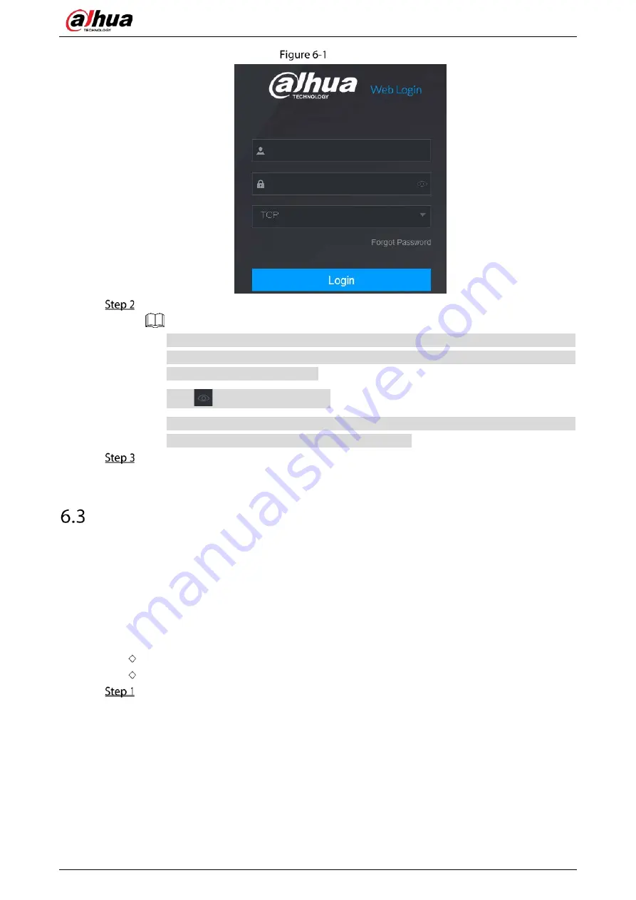
Enter the user name and password. 


The default administrator account is admin. The password is the one that was configured 
during initial settings. To security your account, it is recommended to keep the password 
properly and change it regularly. 


Click 

  to display the password. 


If you forget the password, click Forgot Password to reset the password. For details about 
resetting the password, see "6.3 Resetting Password." 


Click Login. 


Resetting Password 

You can reset the password by the following methods when you forget the password for admin 
account. 


If the password reset function is enabled, you can use mobile phone to scan the QR code on the 
local interface or web interface to reset the password.   


If the password reset function is disabled, the system prompts indicating password resetting 
function is disabled. To reset the password, try either of the following ways: 


Log in to the web with other user account to enable the password reset function. 


Go to local interface to reset the password. For details, see "5.1.3 Resetting Password. 


Log in to the web of the Device. 

Содержание DH-XVR1B04

Страница 1: ...Digital Video Recorder User s Manual V1 5 0 ZHEJIANG DAHUA VISION TECHNOLOGY CO LTD ...

Страница 2: ...5104HE X DH XVR5104HS X1 DH XVR5104C X1 DH XVR5216AN X DH XVR5232AN X DH XVR5104H X1 DH XVR5104HE X1 DH XVR5208AN 4KL X DH XVR5216AN 4KL X DH XVR5216A X DH XVR5432L X DH XVR5832S X DH XVR5108H 4KL X 8P DH XVR5208AN 4KL X 8P DH XVR5216AN 4KL X 16P DH XVR5416L X DH XVR5408L X DH XVR5816S X DH XVR5808S X DH XVR5104H X 4P DH XVR5108H X 8P DH XVR5216AN X 16P XVR7 series DH XVR7104E 4KL X DH XVR7108E 4K...

Страница 3: ...els 2 Replaced two PoC images and updated some descriptions July 2019 V1 3 0 Updated safety baseline functions 1 Match language automatically during initialization change GMT time zone to UTC time zone match PAL and NTSC automatically 2 Password on the local login interface is displayed with plaintext 3 Reboot is not required after service port number is changed 4 Added record control tab 5 Added ...

Страница 4: ...gitimate rights and interests of other people by implementing measures which include but are not limited Providing clear and visible identification to inform people of the existence of the surveillance area and provide required contact information About the Manual The manual is for reference only Slight differences might be found between the manual and the product We are not liable for losses incu...

Страница 5: ...de the reader software or try other mainstream reader software if the manual in PDF format cannot be opened All trademarks registered trademarks and company names in the manual are properties of their respective owners Please visit our website contact the supplier or customer service if any problems occur while using the device If there is any uncertainty or controversy we reserve the right of fin...

Страница 6: ...e Operate the device within the rated range of power input and output Do not dissemble the Device Transport use and store the Device under the allowed humidity and temperature conditions Electrical Safety Use the battery of specified manufacturer otherwise there might result in explosion When replacing battery make sure the same type is used Improper battery use might result in fire explosion or i...

Страница 7: ...6AN 4KL X DH XVR5216A X DH XVR7208A 4KL X DH XVR7216A 4KL X DH XVR7208A 4K X DH XVR5108H 4KL X 8P DH XVR5208AN 4KL X 8P DH XVR5216AN 4KL X 16P DH XVR5216AN X 16P DH XVR7208A 4K X2 13 2 2 6 DH XVR7416L 4KL X DH XVR5432L X 15 2 2 7 DH XVR7816S 4KL X DH XVR5832S X DH XVR7816S 4KL X LP 18 Installing Device into Rack 20 3 The Grand Tour 21 Front Panel 21 3 1 1 DH XVR5108C X DH XVR5104C 4KL X DH XVR5104...

Страница 8: ...108HE 4K X DH XVR5104H X DH XVR5104HE X DH XVR5104H X1 DH XVR5104HE X1 DH XVR7108HE 4K X2 29 3 2 5 DH XVR1B04 DH XVR1B04H DH XVR1B08 DH XVR1B08H DH XVR1B04 V2 DH XVR1B08 V2 31 3 2 6 DH XVR4216AN X DH XVR4232AN X DH XVR5216AN X DH XVR5232AN X DH XVR5208AN 4KL X DH XVR5216AN 4KL X DH XVR5216A X DH XVR7208A 4KL X DH XVR7216A 4KL X DH XVR7208A 4K X DH XVR5216AN X 16P DH XVR7208A 4K X2 32 3 2 7 DH XVR5...

Страница 9: ...Z Functions 108 5 4 4 Calling PTZ Functions 110 5 4 5 Calling OSD Menu 112 Configuring Camera Settings 113 5 5 1 Configuring Image Settings 113 5 5 2 Configuring Encode Settings 116 5 5 3 Configuring Overlay Settings 119 5 5 4 Configuring Covered Area Settings 120 5 5 5 Configuring Channel Type 121 5 5 6 Upgrading Coaxial Camera 122 Configuring Remote Devices 123 5 6 1 Adding Remote Devices 123 5 ...

Страница 10: ...1 Searching the Transaction Records 230 5 13 2 Configuring POS Settings 231 Configuring Backup Settings 232 5 14 1 Finding USB Device 232 5 14 2 Backing up Files 233 Network Management 235 5 15 1 Configuring Network Settings 235 5 15 2 Configuring Network Testing Settings 251 Configuring Account Settings 255 5 16 1 Configuring User Account 256 5 16 2 Configuring Group Account 260 5 16 3 Configurin...

Страница 11: ...3 Viewing Alarm Status Information 305 5 21 4 Viewing Network Information 306 5 21 5 Viewing HDD Information 308 5 21 6 Viewing Channel Information 309 5 21 7 Viewing Data Stream Information 310 5 21 8 Viewing PoC Information 311 Logging out the Device 312 6 Web Operations 313 Connecting to Network 313 Logging in to the Web 313 Resetting Password 314 Web Main Menu 317 7 FAQ 320 Glossary 326 HDD Ca...

Страница 12: ...ng Modes 341 Appendix 7 3 Thunder Proof Ground Method in the Monitor System 342 Appendix 7 4 The Shortcut Way to Check the Electric System by Digital Multimeter 343 RJ45 RS 232 Connection Cable Definition 346 Cybersecurity Recommendations 348 ...

Страница 13: ...s bank telecom electricity traffic intelligent residential district factory warehouse resources and water conservancy facilities Functions The functions might be different depending on the software and hardware version of the model you purchased Smart Detection Smart detection Effectively detect persons and motor vehicles in the video Face detection Effectively recognize faces in the video analyze...

Страница 14: ...iew event accurate occurred time Support zooming in the selected area in the live view Network Operation Support network remote real time monitor remote record search and remote PTZ control Alarm Activation Several relay alarm outputs to realize alarm activation and on site light control The alarm input port and output port have the protection circuit to guarantee the Device safety Communication P...

Страница 15: ... No broken or distorted positions that could be caused by hit 2 Labels Labels on the device Not torn up Do not tear up or throw away the labels otherwise the warranty services are not ensured You need to provide the serial number of the product when you call the after sales service 3 Device Appearance No obvious damage Data cables power cables fan cables mainboard No connection loose Installing HD...

Страница 16: ...4104C X DH XVR4108C X DH XVR5104C X1 DH XVR4104C X1 DH XVR4108C X1 Loosen the screws of the bottom of the chassis Loosen screws Step 2 Place the HDD in accordance with the four holes in the bottom Align HDD Step 3 Turn the device upside down and then secure the screws firmly ...

Страница 17: ... 5 Secure screws Step 4 Connect the HDD cable and power cable to the HDD and the mainboard respectively Connect cables Step 5 Put the cover back and then fix the screws of the rear panel The installation is complete ...

Страница 18: ...4E 4KL X DH XVR7108E 4KL X DH XVR7104E 4KL B X DH XVR7108E 4KL B X 2 2 2 1 Installing Battery The battery is only provided with some models Pull the battery cable through the hole Pull battery cable through hole Connect the cable into the port ...

Страница 19: ...nnect to port 2 2 2 2 Installing HDD Loosen the screws to take off the cover Loosen screws Remove the screws to take off the bracket Take off bracket Fix the HDD to the bracket and then connect power cable and data cable ...

Страница 20: ...User s Manual 8 Fix HDD Connect cables Install the bracket and then fasten the screws ...

Страница 21: ...HS 4KL X DH XVR5108HS 4KL X DH XVR5108H X DH XVR5116H X DH XVR5104H 4KL X DH XVR5108H 4KL X DH XVR5116H 4KL X DH XVR5108HE X DH XVR5116HE X DH XVR7104HE 4KL X DH XVR7108HE 4KL X DH XVR7116HE 4KL X DH XVR7108HE 4K X DH XVR5104HS X DH XVR4104HS X DH XVR5104H X DH XVR5104HE X DH XVR4108HS X DH XVR5104HS X1 DH XVR4104HS X1 DH XVR4108HS X1 DH XVR5104H X1 DH ...

Страница 22: ...the upper cover and side panel Loosen screws Remove the cover in the direction of the arrow as shown in the figure below Remove cover Turn over the device and align the HDD to the four holes of bottom panel and then fix the HDD with screws Fix HDD Connect HDD to the device using data cable and power cable ...

Страница 23: ...crews on the rear panel and side panel Fix screws 2 2 4 DH XVR1B04 DH XVR1B04H DH XVR1B08 DH XVR1B08H DH XVR1B16 DH XVR1B16H DH XVR1B04 V2 DH XVR1B08 V2 Step 1 Loosen the screws of the upper cover Loosen screws Step 2 Remove the cover in the direction of the arrow as shown in the figure below ...

Страница 24: ... over the device and align the HDD to the four holes of bottom panel and then fix the HDD with screws Align HDD Step 4 Connect HDD to the device using data cable and power cable Connect cables Step 5 Put back and fix the cover with the screws ...

Страница 25: ...XVR5216AN 4KL X DH XVR5216A X DH XVR7208A 4KL X DH XVR7216A 4KL X DH XVR7208A 4K X DH XVR5108H 4KL X 8P DH XVR5208AN 4KL X 8P DH XVR5216AN 4KL X 16P DH XVR5216AN X 16P DH XVR7208A 4K X2 Remove the four fixing screws on the rear panel Remove screws Remove the case cover along the direction shown in the following arrow ...

Страница 26: ...ur holes on the baseboard to place the HDD Place HDD Turn the device upside down match the screws with the holes on the HDD and then fasten them The HDD is fixed to the baseboard Fix HDD Connect the HDD data cable and power cable to the device ...

Страница 27: ...nual 15 Connect cables Put back the cover and fasten the four screws on the rear panel to complete the installation Fasten screws 2 2 6 DH XVR7416L 4KL X DH XVR5432L X Remove the fixing screws on the rear panel ...

Страница 28: ...he following arrow Remove cover Remove the screws on the sides of HDD bracket to take out the bracket Remove bracket Match the four screw holes on the HDD with the four holes on the bracket and then fasten the screws The HDD is fixed to the bracket Fix HDD Install the other HDDs ...

Страница 29: ...o the device and then fasten the screws on the sides of the bracket Fasten screws Connect the HDD data cable and power cable to the device Connect cables Put back the cover and fasten the screws on the rear panel to complete the installation Put back cover ...

Страница 30: ...e chassis Remove screws Take off the cover of the chassis Take off cover Remove the screws from the drive bracket to take it off Take off drive bracket Align the four screw holes on the disk to those on the drive bracket and fix the disk on the bracket Fix disk Fix other disks on the bracket as needed ...

Страница 31: ...is is only needed on models with 8 bays Fix drive brackets Put the drive brackets back and fix them in the DVR Put back drive bracket Connect the disks and the DVR with power cable and data cable The following figure shows the connection of 4 bay model for example ...

Страница 32: ... To install the DVR into rack do the following Check whether the in house temperature is lower than 35 C 95 F and make sure the 15 cm 6 inches spacing around the Device for ventilation Use six screws to fix the DVR on each side Install from the bottom up If you want to install more accessories to the rack take preventive measures to avoid power socket overload Optional Install more accessories to ...

Страница 33: ...me Function HDD status indicator The indicator is off when the HDD is running normally The indicator glows blue when the HDD is in malfunction Power status indicator The indicator is off when the power is connected abnormally The indicator glows blue when the power is connected normally Network status indicator The indicator is off when the network connection is correct The indicator glows blue wh...

Страница 34: ...percent the No 5 indicator is on and the others are out When the battery remains between one percent and thirty percent the No 6 indicator is on and the others are out When the battery is exhausted the DVR is turned off or there is no battery attached to the DVR all the three indicators are out 7 USB port Connects to external devices such as USB storage device keyboard and mouse 3 1 3 DH XVR5108H ...

Страница 35: ...ral devices such as USB storage device keyboard and mouse 3 1 4 DH XVR7104HE 4KL X DH XVR7108HE 4KL X DH XVR7116HE 4KL X DH XVR7108HE 4K X DH XVR7108HE 4K X2 Front panel Table 3 4 Front panel description No Port Name Function 1 USB port Connects to peripheral devices such as USB storage device keyboard and mouse 3 1 5 DH XVR4216AN X DH XVR4232AN X DH XVR5216AN X DH XVR5232AN X DH XVR5208AN 4KL X D...

Страница 36: ...is abnormal 3 NET Glows blue when network status is abnormal 4 POWER Glows blue when the power is connected properly 5 USB port Connects to the external devices such as keyboard mouse and USB storage device 3 1 6 DH XVR1B04 DH XVR1B04H DH XVR1B08 DH XVR1B08H DH XVR1B16 DH XVR1B16H DH XVR1B04 V2 DH XVR1B08 V2 Front panel 3 1 7 DH XVR7208A 4KL X DH XVR7216A 4KL X DH XVR7208A 4K X Front panel ...

Страница 37: ...el description No Port Name Function 1 IR receiver Receives infrared signal from remote control 2 USB port Connects to peripheral devices such as USB storage device keyboard and mouse 3 1 9 DH XVR7816S 4KL X DH XVR7816S 4KL X LP Front panel Table 3 8 Front panel description No Port Name Function 1 IR receiver Receives infrared signal from remote control 2 USB port Connects to peripheral devices su...

Страница 38: ...SB port Connects to peripheral devices such as USB storage device keyboard and mouse 3 1 11 DH XVR5832S X DH XVR5808S X DH XVR5816S X Front panel Table 3 10 Front panel description No Port Name Function 1 Status indicator light Glows blue when the device is working properly 2 HDD Glows blue when HDD status is abnormal 3 NET Glows blue when network status is abnormal 4 POWER Glows blue when the pow...

Страница 39: ...es such as USB storage device keyboard and mouse 3 VGA port Outputs analog video data to the connected display with VGA port 4 HDMI port High definition audio and video signal output port The port outputs the uncompressed high definition video and multi channel audio data to the connected display with HDMI port 5 Network port Connects to Ethernet port 6 Power input port Inputs 12 VDC power 7 Groun...

Страница 40: ...such as speed dome PTZ RS 485_A port is connected by the cable A and RS 485_B is connected to the cable B 5 HDMI port High definition audio and video signal output port The port outputs the uncompressed high definition video and multi channel audio data to the connected display with HDMI port 6 VGA port Outputs analog video data to the connected display with VGA port 7 8 USB port Connects to exter...

Страница 41: ...rt The port outputs the uncompressed high definition video and multi channel audio data to the connected display with HDMI port 5 Network port Connects to Ethernet port 6 RS 485 communication port Connects to the control devices such as speed dome PTZ RS 485_A port is connected by the cable A and RS 485_B is connected to the cable B 7 VGA port Outputs analog video data to the connected display wit...

Страница 42: ...device and the Device have the same ground Alarm output port 1 3 NO1 NO3 C1 C3 Three groups of alarm output ports Group 1 port NO1 C1 Group 2 port NO2 C2 Group 3 port NO3 C3 These ports output alarm signal to the alarm device Make sure that power supply to the external alarm device NO Normally open alarm output port C Alarm output public end Ground 2 Video input port Connects to analog camera to i...

Страница 43: ... Inputs 12 VDC power 11 VGA port Outputs analog video data to the connected display with VGA port 12 Power button Turns on off the DVR 13 Power cable fastener Use a cable tie to secure the power cable on the DVR to prevent loss 14 Ground terminal 3 2 5 DH XVR1B04 DH XVR1B04H DH XVR1B08 DH XVR1B08H DH XVR1B04 V2 DH XVR1B08 V2 Rear panel Table 3 14 Rear panel description No Port Name Function 1 Vide...

Страница 44: ... XVR4232AN X DH XVR5216AN X DH XVR5232AN X DH XVR5208AN 4KL X DH XVR5216AN 4KL X DH XVR5216A X DH XVR7208A 4KL X DH XVR7216A 4KL X DH XVR7208A 4K X DH XVR5216AN X 16P DH XVR7208A 4K X2 Rear panel Table 3 15 Rear panel description No Port Name Function 1 Ground terminal 2 Alarm input port 1 16 Four groups of alarm input ports Group 1 port 1 to port 4 Group 2 port 5 to port 8 Group 3 port 9 to port ...

Страница 45: ...inition audio and video signal output port The port outputs the uncompressed high definition video and multi channel audio data to the connected display with HDMI port 7 USB port Connects to the external devices such as keyboard mouse and USB storage device 8 Network port Connects to Ethernet port 9 RS 485 communication port Connects to the control devices such as speed dome PTZ RS 485_A port is c...

Страница 46: ...B storage device 8 HDMI port High definition audio and video signal output port The port outputs the uncompressed high definition video and multi channel audio data to the connected display with HDMI port 9 Network port Connects to Ethernet port 10 RS 485 communication port Connects to the control devices such as speed dome PTZ RS 485_A port is connected by the cable A and RS 485_B is connected to...

Страница 47: ... Group 2 port NO2 C2 Group 3 port NO3 C3 Group 4 port NO4 C4 Group 5 port NO5 C5 NC5 These ports output alarm signal to the alarm device Make sure that power supply to the external alarm device NO Normally open alarm output port C Alarm output public end NC Normally closed alarm output port RS 485 communication port Connects to the control devices such as speed dome PTZ RS 485_A port is connected ...

Страница 48: ...description No Port Name Function 1 GND Ground 2 Power button Turns on off the Device 3 Power input port Inputs power 4 Audio input port Receives the analog audio signal output from the devices such as microphone 5 Audio input port MIC IN Tow way talk input port which receives the analog audio signal output from the devices such as microphone pickup 6 Audio output port MIC OUT Tow way talk output ...

Страница 49: ...plex RS 485 port T T R R Four wire full duplex 485 port T and T is the output wire R and R is the input wire Control power output CTRL 12V Controls the 6th channel power output for alarm Turns off power output when there is alarm output Turns on power output when the alarm is cleared 12V power output port Provides power to external devices such as camera and alarm device Note that the supplying po...

Страница 50: ...8 Video output port Connect to video output devices such as TV 9 Alarm input port 1 16 Four groups of alarm output ports Group 1 port 1 to port 4 Group 2 port 5 to port 8 Group 3 port 9 to port 12 Group 4 port 13 to port 16 These ports receive the signal from the external alarm source There are two types NO Normally Open and NC Normally Closed When your alarm input device is using external power m...

Страница 51: ... Ground 10 Video input port Connect to analog camera to input video signal 11 Network port Connects to Ethernet port 12 VGA video output Outputs analog video signal It can connect to the monitor to view analog video 13 RS 232 debug COM It is for general COM debug to configure IP address or transfer transparent COM data 14 HDMI port High definition audio and video signal output port It outputs the ...

Страница 52: ... NC Normally Closed When your alarm input device is using external power make sure that the device and the NVR have the same ground Alarm output port 1 5 NO1 NO5 C1 C5 NC5 Five groups of alarm output ports Group 1 port NO1 C1 Group 2 port NO2 C2 Group 3 port NO3 C3 Group 4 port NO4 C4 Group 5 port NO5 C5 NC5 These ports output alarm signal to the alarm device Make sure that power supply to the ext...

Страница 53: ...cts to the external devices such as keyboard mouse and USB storage device 16 eSATA port External SATA port which connects to the device with SATA port Perform the jumper configuration when connecting HDD 3 2 12 DH XVR7816S 4KL X LP Rear panel Table 3 21 Rear panel description No Port Name Function 1 Audio output port Outputs the analog audio signal to the devices such as the sound box 2 Video outp...

Страница 54: ... 485_B is connected to the cable B Four wire full duplex RS 485 port T T R R Four wire full duplex 485 port T and T is the output wire R and R is the input wire Control power output CTRL 12V Controls the 6th channel power output for alarm Turns off power output when there is alarm output Turns on power output when the alarm is cleared 12V power output port Provides power to external devices such a...

Страница 55: ...s microphone 3 Audio output port Outputs the analog audio signal to the devices such as the sound box 4 GND Ground 5 Power cable fastener Use clamp to secure the power cable on the DVR in case there is any loss 6 VGA video output Outputs analog video signal It can connect to the monitor to view analog video 7 HDMI port High definition audio and video signal output port It outputs the same video so...

Страница 56: ...orts 4K resolution output and supports mouse operation and control Note when the HDMI output resolution is 4K the VGA output stops 5 Network port Connects to Ethernet port 6 RS 485 communication port Connects to the control devices such as speed dome PTZ RS 485_A port is connected by the cable A and RS 485_B is connected to the cable B 7 USB port Connects to external devices such as USB storage de...

Страница 57: ...as VGA It supports 4K resolution output and supports mouse operation and control Note when the HDMI output resolution is 4K the VGA output stops 6 VGA video output Outputs analog video signal It can connect to the monitor to view analog video 7 Network port Connects to Ethernet port 8 RS 485 communication port Connects to the control devices such as speed dome PTZ RS 485_A port is connected by the...

Страница 58: ...this button to play back the next video 6 Previous record In playback state press this button to play back the previous video 7 Play Pause In normal playback state press this button to pause playback In pause state press this button to resume to normal playback In live view window interface press this button to enter video search menu 8 Reverse pause In the reverse playback state press this button...

Страница 59: ... control menu in PTZ control interface In motion detection interface press this button with direction keys to complete setup In text mode press and hold this button to delete the last character To use the clearing function Long press this button for 1 5 seconds In HDD menu switch HDD recording time and other information as indicated in the pop up message 15 Alphanumeric keys Input password numbers...

Страница 60: ...k the video In multiple window mode double click one channel to view in full window Double click current video again to go back to previous multiple window mode Right click Right click in live view window interface the shortcut menu is displayed For different series product the shortcut menu may vary Exit current menu without saving the modification Click scroll wheel button In numeral input box I...

Страница 61: ... Basics This chapter introduces the typical connection diagrams and ports connections Typical Connection Diagram The following figure is for reference only The actual product shall prevail Typical connection 1 Typical connection 2 ...

Страница 62: ... compensation devices or use optical fiber to ensure video quality You should keep the video signal away from the strong electromagnetic interference especially the high tension current Keeping connection lugs in well contact The signal line and shielded wire should be fixed firmly and in well connection Avoid dry joint lap welding and oxidation 4 2 2 Video Output Video output includes a BNC PAL N...

Страница 63: ...eded for alarm input Alarm input needs the low level voltage signal Alarm input mode can be either NC Normally Closed or NO Normally Open When you are connecting two DVRs or you are connecting one DVR and one other device use a relay to separate them Alarm output The alarm output port should not be connected to high power load directly It shall be less than 1 A to avoid high current which might re...

Страница 64: ...elled open the power output 12V Rated current Voltage current 500 mA Ground cable 485 A B 485 communication port They are used to control devices such as decoder 120 Ω should be parallel connected between A B lines if there are too many PTZ decoders T T R R Four wire full duplex RS 485 port T T output wire R R input wire 4 3 2 Alarm Input Refer to the following figure for more information Groundin...

Страница 65: ...d plating AuAg10 AgNi10 CuNi30 Rating Resistance Load Rated switch capacity 30 VDC 1 A 125 VAC 0 5 A 24 VDC 1 A 125 VAC 2 A Maximum switch power 62 5 VA 30 W 250 VA 48 W Maximum switch voltage 125 VAC 60 VDC 125 VAC 60 VDC Maximum switch currency 2 A 2 A Insulation Between touches 400 VAC 1 minute 500 VAC 1 minute Between touch and winding 1000 VAC 1 minute 1000 VAC 1 minute Turn on Time 5 ms max ...

Страница 66: ...RS 485 Port Connect the RS 485 cable of the PTZ camera to the RS 485 port on the Device Ensure the match of A and B interfaces Connect the video out cable of the PTZ camera to the video input port on the Device Turn on the PTZ camera ...

Страница 67: ...ice Power on the Device after the power cable is properly connected To protect the Device please connect the Device with the power cable first and then connect to the power source To ensure the stable work of the Device and the external devices connected to the Device and to prolong the batter life it is recommended to refer to the national related standard to use the power source that provides st...

Страница 68: ...he Device Turn on device Select your location from the drop down list then language and video standard will match your location automatically You can change the language and video standard manually Click Next The Dahua Software License Agreement interface is displayed License agreement Select I have read and agree to all terms and then click Next ...

Страница 69: ...1 Password setting parameters Parameter Description User By default the user is admin Password In the Password box enter the password for admin Confirm Password Prompt Hint In the Prompt Hint box enter the information that can remind you of the password On the login interface click the prompt will display to help you find back the password Click Next ...

Страница 70: ... system will require the unlock pattern as the default login method If you skip this setting enter the password for login Password protection Configure the protection parameters for password After configuration if you forget the password for admin user you can reset the password through the reserved email address or security questions For details about resetting the password see 5 1 3 If you do no...

Страница 71: ... and agree to all terms check box Click Next The Startup Wizard interface is displayed For details about quick settings during startup see 5 1 4 Setting Up with the Startup Wizard 5 1 3 Resetting Password You can reset the password by the following methods when you forget the password for admin account If the password reset function is enabled you can use mobile phone to scan the QR code to reset ...

Страница 72: ...word on local interface make sure that security questions are preset when the device does not support Reset button 5 1 3 2 Resetting Password on Local Interface Enter the login interface If you have configured unlock pattern the unlock pattern login interface is displayed Click Forgot Pattern the password login interface is displayed If you did not configure unlock pattern the password login inter...

Страница 73: ... you have set the reserved email address the Prompt message interface is displayed If you did not set the reserved email address the email entering interface is displayed Enter the email address and then click Next the Prompt message interface is displayed ...

Страница 74: ...K the system will collect your information for password reset and the information includes but not limited to email address MAC address and device serial number Read the prompt carefully before clicking OK Password reset 1 Reset the password QR code ...

Страница 75: ...ce Use the security code received in your email box to reset the password within 24 hours otherwise the security code becomes invalid Security questions 1 On the Reset password interface as shown in Step 3 in the Reset Type list select Security Questions the Security Questions interface is displayed If you did not configure the security questions before in the Reset Type list there will be no Secu...

Страница 76: ...ssword box Click Save The password resetting is started After resetting is completed a pop up message is displayed Click OK A pop up message is displayed asking if you want to sync the password with the remote devices Click Cancel the resetting is finished Click OK the Sync Info interface is displayed Password reset 4 ...

Страница 77: ... button on the mainboard to reset the Device to the factory default Not all models are provided with reset button Disconnect the Device frompower source and then remove the cover panel For details about removing the cover panel see 2 2 Installing HDD Find the reset button on the mainboard and then press and hold the reset button for 5 seconds to 10 seconds Reset button Restart the Device ...

Страница 78: ...updates are available After the auto check function is enabled to notify you to update timely the system will collect the information such as IP address device name firmware version and device serial number The collected information is only used to verify the legality of the Device and push upgrade notices If you clear the Auto check for updates check box the system will not perform automatic chec...

Страница 79: ... the standby time for the Device The Device automatically logs out when it is not working for the configured time period You need to log in to the Device again The value ranges from 0 to 60 0 indicates there is not standby time for the Device Click Monitor Channel s when logout You can select the channels that you want to continue monitoring when you logged out Navigation Bar Enable the navigation...

Страница 80: ...ended to avoid the recoding period or stop recording first before you change the system time Time Zone In the Time Zone list select a time zone for the system Date Format In the Date Format list select a date format for the system Date Separator In the Date Separator list select a separator style for the date Time Format In the Time Format list select 12 HOUR or 24 HOUR for the time display style ...

Страница 81: ...NETWORK TCP IP After you have configured the date and time settings on the Date Time interface click Next Configure the settings for network parameters Table 5 4 Network parameters Parameter Description IP Version In the IP Version list you can select IPv4 or IPv6 Both versions are supported for access MAC Address Displays the MAC address of the Device DHCP Enable the DHCP function The IP address ...

Страница 82: ...e as below 1500 The biggest value of Ethernet information package This value is typically selected if there is no PPPoE or VPN connection and it is also the default value of some routers network adapters and switches 1492 Optimized value for PPPoE 1468 Optimized value for DHCP 1450 Optimized value for VPN Test Click Test to test if the entered IP address and gateway are interworking 5 1 4 5 Config...

Страница 83: ...tform Then you can access and manage the device in the WAN For details refer to the P2P operation manual You can also enter the QR code of Cell Phone Client and Device SN by clicking on the top right of the interfaces after you have entered the Main Menu If selection of this function is canceled the Note interface is displayed See Figure 5 21 Choose to enable it or not according to your actual nee...

Страница 84: ... sure the Device is initialized is displayed 3 Tap OK If the Device has not been initialized Tap Device Initialization to perform initializing by following the onscreen instructions If the Device has been initialized you can start adding it directly 4 Tap Add Device You can add wireless device or wired device The Manual takes adding wired device as an example ...

Страница 85: ...3 Add device 5 Tap P2P P2P 6 Enter a name for the DVR the username and password scan the QR code under Device SN 7 Tap Start Live Preview The Device is added and displayed on the live view interface of the cell phone ...

Страница 86: ...settings of main stream and sub stream for the Device You can also configure encode settings by selecting Main Menu CAMERA Encode Audio Video After you have configured the P2P settings on the Audio Video interface click Next Encode Configure the settings for the main sub streams parameters ...

Страница 87: ...PAL format you can select the value from 1 through 25 in NTSC format you can select the value from 1 through 30 However the actual range of frame rate that you can select depends on the capability of the Device Bit Rate Type In the Bit Rate Type list select CBR Constant Bit Rate or VBR Variable Bit Rate If you select CBR the image quality cannot be configured if you select VBR the image quality ca...

Страница 88: ...ect the channel that you want to configure the settings for Type In the Mode list you can select Human Face Event or General as the event type for which you want to take a snapshot Scheduled The snapshot is taken during the scheduled period Event The snapshot is taken when there is an alarm event occurs such as motion detection event video loss and local alarms Face Snapshot The snapshot is taken ...

Страница 89: ...e recorded video files always from the earliest time The locked recorded video files will not be overwritten Create Video Files Configure the time length and file length for each recorded video Delete Expired Files Configure whether to delete the old files and if yes in the Delete Expired Files list select Custom to configure the time length for how long you want to keep the old files 5 1 4 9 Conf...

Страница 90: ... then set a HDD as redundant HDD Select Main Menu STORAGE Schedule Record and then select the Redundancy check box If the selected channel is not recording the redundancy function takes effect next time you record no matter you select the check box or not If the selected channel is recording the current recorded files will be packed and then start recording according to the new schedule Not all mo...

Страница 91: ...eriods Define for the whole week Click next to All all the icon switches to you can define the period for all the days simultaneously Define for several days of a week Click before each day one by one the icon switches to You can define the period for the selected days simultaneously 3 On the timeline drag to define a period The Device starts recoding the selected event type in the defined period ...

Страница 92: ...s to other channels After configuring the recording schedule settings you need to perform the following operations to start recording according to the defined schedule Enable the alarm event and cofigure the settings for the recording channel For details see 5 10 Alarm Events Settings You need to enable the recording function see 5 9 1 Enabling Record Control 5 1 4 10 Configuring Snapshot Storage ...

Страница 93: ...tting is active For details about defining a period see 5 1 4 9 Configuring Recorded Video Storage Schedule Copy Click Copy to to copy the settings to other channels Click OK A pop up message is displayed Click OK The live view screen is displayed The setting up with startup wizard is completed You can start using the Device Optional After the setting with startup wizard is completed if the connec...

Страница 94: ... View After you logged in the Device the live view is displayed The number of channels displayed depends on your model To enter the live view screen from other interfaces click on the top right of the screen Live view 5 2 1 Live View Screen ...

Страница 95: ...con Function Indicates recording status This icon displays when the video is being recorded This icon displays when the motion detection occurs in the scene This icon displays when the video loss is detected This icon displays when the channel monitoring is locked To switch the position of two channels point to one of the two channels and then drag the window to the other channel 5 2 2 Live View C...

Страница 96: ... Analog channel Digital channel Table 5 11 Live control bar description No Function No Function No Function 1 Instant Playback 4 Manual Snapshot 7 Camera Registration 2 Digital Zoom 5 Mute 3 Instant Record 6 Audio Talk ...

Страница 97: ...ant playback and will not display until exited During playback screen split layout switch is not allowed To change the playback time select Main Menu SYSTEM General Basic in the Instant Play box enter the time you want to play back General 5 2 2 2 Digital Zoom You can enlarge a specific area of the image to view the details by either of the following two ways Click the icon switches to Hold down t...

Страница 98: ...rage device By clicking you can take snapshots The snapshots are automatically saved into the connected USB storage device You can view the snapshots on your PC To change the quantity of snapshots select Main Menu CAMERA Encode Snapshot in the Manual Snapshot list select the snapshot quantity 5 2 2 5 Mute Analog channel only You can mute the video sound by clicking This function is supported in si...

Страница 99: ...guring Remote Devices 5 2 3 Navigation Bar You can access the functions to perform operations through the function icons on the navigation bar For example you can access Main Menu and switch window split mode See Figure 5 39 The navigation bar is disabled by default It does not appear in the live view screen until it is enabled To enable it select Main Menu SYSTEM General Basic enable the Navigati...

Страница 100: ...r details see 5 15 1 Configuring Network Settings Open the Disk Manager interface For details see 5 18 3 Configuring Disk Manager Open the USB Management interface For details about USB operations see 5 14 2 Backing up Files 5 21 2 Viewing Log Information 5 20 4 Exporting and Importing System Settings 5 20 6 Updating the Device 5 2 4 Shortcut Menu You can quickly access some function interfaces su...

Страница 101: ... the live view screen as a single channel layout or multi channel layout Previous Screen Click Previous Screen to go to the previous screen For example if you are using 4 split mode the first screen is displaying the channel 1 4 click Next screen you can view channel 5 8 Next Screen Add Camera Open the Camera List interface This parameter displays on the right click menu only after setting at leas...

Страница 102: ... function Image Open the Image interface where you can adjust the video image color Camera Property Click to modify the camera properties Sub Port Click to switch to extra screen control 5 2 5 Channel Sequence You can adjust the channel sequence displayed on live interface on actual needs The live view interface displays the default channel sequence after restoring factory defaults Right click on ...

Страница 103: ...nce Drag a channel to the target window split Drag a window split to another to change the sequence You can view the channel sequence according to the channel number on the lower right corner of the window split Adjust sequence 5 2 6 Color Setting ...

Страница 104: ...d then select Image the Image interface is displayed For details see 5 5 1 Configuring Image Settings Image Table 5 14 Image settings Parameter Description Period Divide 24 hours into two periods and configure the corresponding color settings Effective Time Enable the function and then set the effective time for each period Sharpness Adjust the sharpness of image edge The bigger the value is the m...

Страница 105: ...om 0 to 100 The default value is 50 The recommended range is between 40 and 60 Saturation Adjust the color shades The bigger the value the lighter the color will become This value does not influence the general image lightness The value ranges from 0 to 100 The default value is 50 The recommended range is between 40 and 60 Color Mode In the Color Mode list you can select Standard Soft Bright Vivid...

Страница 106: ...If you select All the configuration will apply to all four customized color modes 3 Click OK 4 On the Image interface in the Color Mode list you can select the customized color mode 5 2 7 Live View Display 5 2 7 1 Configuring Display Settings You can configure the display effect such as displaying time title and channel title adjusting image transparency and selecting the resolution Select Main Me...

Страница 107: ...ansparency of the graphical user interface GUI The higher the value the more transparent the GUI becomes Resolution Select resolution for the video The default resolution for VGA port and HDMI port is 1280 1024 Some of the resolution options might not be supported on the HDMI port Live Mode General No information is displayed on the channel window Face Displays the detected face snapshots taken as...

Страница 108: ... Zero channel Configure the settings for the zero channel parameters Table 5 16 Zero channel parameters Parameter Description Enable Enable zero channel function Compression In the Compression list select the video compression standard according to the device capability The default is H 264 Resolution In the Resolution list select the video resolution The default is 704 576 D1 Frame Rate FPS Selec...

Страница 109: ...gins in top bottom left and right directions as well as the brightness of the monitor connected to the Video out port of the Device Select Main Menu DISPLAY TV Adjust TV adjustment Configure the parameters according to your actual situation Click Apply to complete the settings 5 2 8 Configuring Tour Settings You can configure a tour of selected channels to repeat playing videos The videos display ...

Страница 110: ...User s Manual 98 Main screen Sub screen Configure the settings for the tour parameters for both Main Screen and Extra Screen ...

Страница 111: ...ls to form a group and then click Save Delete a channel group Select the check box of any channel group and then click Delete Edit a channel group Select the check box of any channel group and then click Modify or double click on the group The Modify Channel Group dialog box is displayed You can regroup the channels Click Move up or Move down to adjust the position of channel group Click Apply On ...

Страница 112: ... and click OK to complete the settings Modify channel group 5 2 9 Quick Operation Bar You can quickly access to the function modules on function titles and setting menu through shortcut icons on quick operation bar This topic uses ALARM and CAMERA an example to show you how to quickly access other modules Shortcut Icons on Function Titles Click ALARM to enter the ALARM interface ...

Страница 113: ...erface Click to jump to ALARM interface Click to jump to SMART DETECTION interface Click to jump to POS interface Click to jump to NETWORK interface Click to jump to MAINTAIN interface Click to jump to BACKUP interface Click to jump to DISPLAY interface Click to jump to AUDIO interface Shortcut Icons on Setting Menu ...

Страница 114: ...MERA interface Click to jump to NETWORK interface Click to jump to STORAGE interface Click to jump to SYSTEM interface Click to jump to SECURITY interface Click to jump to ACCOUNT interface Entering Main Menu Right click on the live view screen the shortcut menu is displayed Click Main Menu and then log in to the system The Main Menu is displayed ...

Страница 115: ...User s Manual 103 Main menu ...

Страница 116: ...annel function AUDIO Manage audio files and configure the playing schedule The audio file can be played in response to an alarm event if the voice prompts function is enabled 2 Switch icon indicates the current page of main menu Click to switch to the next page or click or to turn page 3 Setting menu Includes six configurations through which you can configure camera settings network settings stora...

Страница 117: ...ice 5 4 1 Configuring PTZ Connection Settings You need to configure the PTZ connection settings before use Local connection RS 485 Port for connecting speed dome or coaxial cable for connecting coaxial camera Remote connection local area network Select Main Menu CAMERA PTZ PTZ Configure the settings for the PTZ connection parameters Table 5 21 PTZ parameters Parameter Description Channel In the Ch...

Страница 118: ...e with the address configured on the PTZ camera otherwise the PTZ camera cannot be controlled from the Device Baud Rate In the Baud Rate list select the baud rate for the PTZ camera The default is 9600 Data Bits The default value is 8 Stop Bits The default value is 1 Parity The default value is NONE Click Apply to save the settings Click Copy to to copy the settings to other channels 5 4 2 Working...

Страница 119: ...to this point and move it to the middle of the screen Zooming On the fast positioning screen drag to draw a square on the view The square supports zooming Dragging upward is to zoom out and dragging downward is to zoom in The smaller the square the larger the zoom effect Not all models support this function and can only be controlled through mouse operations Click you can control the four directio...

Страница 120: ...control panel Table 5 23 PTZ control panel description Icon Function Icon Function Preset Pan Tour Flip Pattern Reset Autoscan Click the AUX Config icon to open the PTZ functions settings interface AUX Switch Click the Enter Menu icon to open the MENU OPERATION interface 5 4 3 Configuring PTZ Functions 5 4 3 1 Configuring Presets On the expanded PTZ control panel click ...

Страница 121: ...ck Click the Tour tab Tour In the Tour No box enter the value for the tour route In the Preset box enter the preset value Click Add Preset A preset will be added for this tour You can repeat adding more presets Click Delete Preset to delete the preset for this tour This operation can be repeated to delete more presets Some protocols do not support deleting 5 4 3 3 Configuring Patterns On the expan...

Страница 122: ...ting zoom focus iris and directions On the PTZ interface click End to complete the settings 5 4 3 4 Configuring Scan On the expanded PTZ control panel click Click the Scan tab Scan Click the direction arrows to position the left and right limits 5 4 4 Calling PTZ Functions After you have configured the PTZ settings you can call the PTZ functions for monitoring from the expanded PTZ control panel ...

Страница 123: ... box enter the value of the tour that you want to call Click to call the tour Click again to stop calling the tour 5 4 4 3 Calling Patterns On the expanded PTZ control panel in the No box enter the value of the pattern that you want to call Call to call the pattern The PTZ camera moves according to the configured pattern repeatedly Click again to stop calling the pattern 5 4 4 4 Calling Scan On th...

Страница 124: ... 6 Using Auxiliary Button On the expanded PTZ control panel click the AUX setting interface is displayed In the Shortcut Aux list select the option that corresponds to the applied protocol In the Aux No box enter the number that corresponds to the AUX switch on the decoder Auxiliary 5 4 5 Calling OSD Menu For the coaxial camera you can call the OSD menu through the expanded PTZ control panel On th...

Страница 125: ...lect the onscreen parameters Click Enter to complete the settings Configuring Camera Settings 5 5 1 Configuring Image Settings You can configure the image settings such as saturation contrast brightness sharpness for each connected camera Select Main Menu CAMERA Image Analog channel ...

Страница 126: ...tive Time box enter the start time and end time for the period you selected Saturation Adjusts the color shades The bigger the value the lighter the color will become This value does not influence the general image lightness The value ranges from 0 to 100 The default value is 50 The recommended range is between 40 and 60 Contrast Adjusts the image contrast The bigger the value is the more obvious ...

Страница 127: ...the parameters correspondingly Day Apply the configuration during daytime Night Apply the configuration during nighttime Normal Apply the configuration during day and night Switch by Period If you select this option you need to configure the sunrise time and sunset time where you are located Mirror Enable the function the left and right side of the video image will be switched It is disabled by de...

Страница 128: ...e image only By Time The camera outputs image according to the configured sunrise time and sunset time Click Apply to complete the settings 5 5 2 Configuring Encode Settings 5 5 2 1 Encode Select Main Menu CAMERA Encode Audio Video Encode Configure the settings for the main sub streams parameters Table 5 25 Main and sub stream parameters Parameter Description Channel In the Channel list select the...

Страница 129: ...er the specific range of frame rate that you can select depends on the capability of the Device Quality This function is available if you select VBR in the Bit Rate List The higher the value the better the image will become I Frame Interval The interval between two reference frames Bit Rate Kb S In the Bit Rate list select a value or enter a customized value to change the image quality The bigger ...

Страница 130: ...he snapshot is taken when there is an alarm event occurs such as motion detection event video loss and local alarms Face Snapshot The snapshot is taken when the face is detected The face detection function is support only with the Channel 1 Size In the Size list select a value for the image The bigger the value is the better the image will become Quality Configures the image quality by 6 levels Th...

Страница 131: ...bled by default After it is enabled when main stream resolution is 4K the frame rate can be 10 fps Select Main Menu CAMERA Encode Encode Enhancement Encode enhancement Click behind Encode Enhancement to enable this function 5 5 3 Configuring Overlay Settings You can configure to display system time and channel name on each channel window in the live view screen Select Main Menu CAMERA Overlay Over...

Страница 132: ... the system time on each channel window in the live view screen In the Time Title list select time display style Channel Title Select the Channel Title check box to display the channel name on each channel window in the live view screen In the Channel Title box enter the name for the selected channel Click Apply to complete the settings Click Copy to to copy the settings to other channels 5 5 4 Co...

Страница 133: ...o apply the configured covered block to the selected channel window during recording To configure covering block do the following 1 Select the Live check box or the Record check box or select the both The 1 2 3 4 buttons are activated 2 Click the buttons to select blocks A triangle solid black block is displayed 3 Drag the block to the area that you want to cover and adjust the size of the block Y...

Страница 134: ...el 8 in Figure 5 72 The 17 32 channels are only for IP camera and the range changes dependent on the model you purchased The channel selection for analog camera or IP camera are in sequence for example if you want to select channels for IP camera you need to select from the last channel number Channel 16 first which means you cannot jump to select the channel 15 directly until you have selected th...

Страница 135: ...nnel that you want to upgrade Click Update If the upgrading is successful the system pops up a message indicating the upgrading is completed Configuring Remote Devices 5 6 1 Adding Remote Devices This function is available after you have configured the channel type as IP channel as described in previous section see 5 5 5 Configuring Channel Type You can add remote devices by IP address Select Main...

Страница 136: ... list None Display all types of devices IPC Display the front end devices DVR Display all storage devices such as NVR DVR and HCVR OTHER Display the devices that do not belong to IPC or DVR type Searched Device List Displays the searched devices You can view the device information such as status IP address Search Click Search the searched devices display in the searched device list To adjust the d...

Страница 137: ... device and then click Delete to delete the added device Import Select the searched devices and then click Import to import the devices in batches Export Select the added devices and then click Export The exported devices information is saved into the USB storage device 5 6 1 1 Initializing Remote Devices You can reset the password and IP address of the remote devices through initializing Click Se...

Страница 138: ...ure the password and email information If you select the Using current device password and email info check box the remote device automatically uses the current password and email information so you do not need to set the password and email address again and can go to Step 6 1 Clear the Using current device password and email info check box ...

Страница 139: ...haracters and contain at least two types of characters among upper case lower case number and special character excluding and Enter a strong password according to the password strength bar indication Confirm Password 3 Click Next Password protection 4 Select the Email Address box and enter the email address that you want to reserve for password reset in the future If you do not want to set the res...

Страница 140: ...ubnet mast default gateway and incremental value The system will allocate the IP address to the remote devices by progressively increasing the last part of the IP address when initializing devices in batches When configuring IP address for multiple remote devices which were not in the same network segment these remote devices will belong to the same network segment after configuration Click Next T...

Страница 141: ... 129 Device initialization Click Finished 5 6 1 2 Adding Remote Devices Automatically On the Add Camera interface click Search Device The devices found are displayed Search device Select the check box of the device ...

Страница 142: ... device Manufacturer In the Manufacturer list select the manufacturer of the remote device IP Address In the IP Address box enter the IP address of remote device The default is 192 168 0 0 which the system cannot connect to RTSP Port The default value setting is 554 You can enter the value according to your actual situation HTTP Port The default value setting is 80 You can enter the value accordin...

Страница 143: ...UDP or MULTICAST If the remote device is added through other manufacturers the system supports TCP and UDP Encryption If the remote device is added through ONVIF protocol enabling the Encryption check box will provide encryption protection to the data being transmitted To use this function the HTTPS function should be enabled for the remote IP camera Click OK to save the settings Only one device c...

Страница 144: ...vice Select the check box of the devices that you want to delete and then click Delete 5 6 1 5 Modifying IP Address You can modify a single IP address or multiple IP addresses of remote devices at one time You can only modify the IP address of initialized cameras To modify a single IP address do the following In the Searched Device list area click for the device that you want to modify IP ...

Страница 145: ...password Click OK To modify IP address in batches do the following In the Searched Device list area select the devices that you want to modify IP address in batches Click Incremental value Set incremental value The system will add the incremental value to the fourth segment of IP addresses of selected devices ...

Страница 146: ...e to the USB port of the Device Click Export Browse Configure the save path Click OK to save the settings A pop up message indicating Successfully exported is displayed Click OK When exporting IP address the Backup Encryption check box is selected by default The file information includes IP address port channel number manufacturer user name and password If you select the Backup Encryption check bo...

Страница 147: ... OK to replace the existing one Click Cancel to add it as a separate device in the Added Device area You can edit the exported csv file and be cautious not to change the file format otherwise the file cannot be imported as it will be judged as invalid The language of csv file must match the Device language The import and export through customized protocol is not supported 5 6 2 Managing Remote Dev...

Страница 148: ...ra List Status Status 5 6 2 2 Viewing Firmware Information You can view the device firmware information such as channel number IP address manufacturer system version video input audio input and alarm in Select Main Menu CAMERA Camera List Firmware ...

Страница 149: ...User s Manual 137 Firmware 5 6 2 3 Upgrading Remote Devices Select Main Menu CAMERA Camera List Update Update Upgrade the device ...

Страница 150: ...date The system will pop up a message to indicate if the upgrading is successful You can use the Type list to filter the devices so that you can find the devices quickly Configuring Record Settings You can record video manually or automatically and configure the recording settings to main stream and sub stream respectively 5 7 1 Enabling Record Control Manual recording operation requires the user ...

Страница 151: ...cording for 24 hours for the selected channel Stop Do not record Snapshot Enable or disable the scheduled snapshot for the corresponding channels Click Apply 5 7 2 Configuring Recorded Video Storage Schedule You need to configure the storage schedule for the recorded video so that the recorded video can be saved For details see 5 1 4 9 Configuring Recorded Video Storage Schedule Configuring Snapsh...

Страница 152: ...layed On the shortcut menu select Manual Control Record Control In the Snapshot area enable the snapshot for the channels if needed Snapshot Select Main Menu CAMERA Encode Snapshot In the Type list select Scheduled and then configure other parameters Scheduled Click Apply to save the settings If you have configured the snapshot schedule the configuration has been completed If you have not configur...

Страница 153: ...apshot In the Type list select Event and then configure other parameters Event Select Main Menu ALARM Video Detection and select the event type to configure for example select the Motion Detection tab Motion detection Click Setting next to Picture Storage check box and select the corresponding channel Click Apply ...

Страница 154: ...Encode Snapshot In the Type list select Face Snapshot and then configure other parameters Face snapshot Select Main Menu SMART DETECTION Parameters Face Picture storage Select the Picture Storage check box and select the corresponding channel Click Apply 5 8 2 Configuring Snapshot Storage Schedule ...

Страница 155: ...or details see 5 18 9 Configuring FTP Storage Settings The snapshots will be uploaded to FTP for backup Playing Back Video 5 9 1 Enabling Record Control Manual recording operation requires the user have the permission to access STORAGE settings Check to ensure the HDD installed in the Device has been formatted properly To enter the record control interface do the following Right click on the live ...

Страница 156: ...configured in the recording schedule Manual Keep general recording for 24 hours for the selected channel Stop Do not record Snapshot Enable or disable the scheduled snapshot for the corresponding channels 5 9 2 Instant Playback You can use the instant playback function to play back the previous five minutes to sixty minutes of the recorded video in any channel For details about instant playback fu...

Страница 157: ...in single channel 4 channel 9 channel and 16 channel When playing back in a single channel click and hold to select the area that you want to enlarge The area is enlarged after the left mouse button is released To exit the enlarged status right click on the image 2 Playback Controls Bar Playback control buttons For details about the control buttons see 5 9 3 1 Introducing Playback Controls ...

Страница 158: ...orded video located Click and hold the time bar and the mouse pointer shall change to a hand icon and then you can drag to view the playback of the target time You can drag the vertical orange line on the time bar to rapidly view the playback in iframe format When playing back video in one channel mode you can move mouse pointer to time bar to display thumbnail pictures for the video of target tim...

Страница 159: ...video files For details see 5 9 3 4 Backing up Recorded Video 11 List Display This area includes Tag List and File List Click the Tag List button the marked recorded video list is displayed Double click the file to start playing Click the File List button the searched recorded video list is displayed You can lock the files For details see 5 9 8 Using the File List 12 Full Screen Click to display i...

Страница 160: ...ton switches to click to stop playing backward During playing back click to start playing forward Previous Frame Next Frame When the playback is paused click or click to play single frame recorded video When playing back single frame recorded video click to start playing forward Slow Playback During playing back click to set the speed of slow playback as SlowX1 2 SlowX1 4 SlowX1 8 or SlowX1 16 Dur...

Страница 161: ... the recorded view For details about adding mark see 5 9 5 Marking and Playing Back Video Hide POS Hide During single channel playback click to display or hide POS information on the screen 5 9 3 2 Selecting Search Type You can search the recorded videos splice or snapshots from HDD or external storage device From R W Disk Recorded videos or snapshots playback from HDD of the Device R W HDD From I...

Страница 162: ...p clipping Click The BACKUP dialog box is displayed You can back up the files You can clip the video of a single channel or multiple channels Maximum 1024 files can be backed up at one time The files that are selected in the File List cannot be clipped 5 9 3 4 Backing up Recorded Video You can back up the recorded video file or splice video file into the USB storage device Select the recorded vide...

Страница 163: ...nnel by selecting Main Menu ALARM Video Detection Motion Detection To use the Smart Search function do the following Select Main Menu SEARCH the video search interface is displayed In the Camera Name list select the channel s that you want to play Click or double click anywhere in the time bar colored area to start playback Click The grid is displayed on the screen Only single channel supports sma...

Страница 164: ...ck Video You can mark the recording for somewhere important Then you can easily find the marked recording by searching time and mark name Marking a Video Select Main Menu SEARCH In the playback mode click Add tag In the Tag Name box enter a name Click OK This marked video file displays in the Tag List Playing Back Marked Video This function is supported on single channel playback In the Camera Nam...

Страница 165: ... of the tagged video before the tagged time In the Tag Name box enter the name of a tagged video In the Interval Before Tag box enter N seconds Click The playback starts from N seconds before the tagged time If there is N seconds exist before the marked time the playback starts from N seconds before the tagged time If there is not it plays back as much as there is Managing Tagged Video In the Tag ...

Страница 166: ...the tagged video and then click Delete After opening the Tag Management interface the playback will pause until exiting this interface If the marked video that was in playing back is deleted the playback will start from the first tagged video in the Tag List 5 9 6 Playing Back Snapshots You can search and play back the snapshots Select Main Menu SEARCH the video search interface is displayed In th...

Страница 167: ...ayback starts from the beginning Double click anywhere on the time bar the playback starts from where you click Time bar Every recorded video file must be at least five minutes If a recorded video file is less than 20 minutes but still choose to split into four windows the system will automatically adjust the windows quantity to ensure every splice is more than five minutes and in this case it is ...

Страница 168: ...ce you can enter the specific time to search the file that you want to view In the File List area there are 128 files can be displayed File type R indicates general recorded video A indicates recorded video with external alarms M indicates recorded video with motion detection events I indicates recorded video with intelligent vents Click to return to the interface with calendar and CAM NAME list ...

Страница 169: ... be covered To view the locked information click the File Lock interface is displayed The recorded video that is under writing or overwriting cannot be locked To unlock the recorded video in the File Lock interface select the video and then click Unlock File lock Alarm Events Settings 5 10 1 Alarm Information You can search view and back up the alarm information Select Main Menu ALARM Alarm Info ...

Страница 170: ... 2 Alarm Input Settings Connect the alarm input and output ports by referring to 4 3 Connecting to Alarm Input and Output You can configure the alarm settings for each channel individually or apply the settings to all channels and then save the settings 5 10 2 1 Configuring Local Alarms You can connect the alarm device to the alarm input port of the Device When the alarm is activated on the alarm ...

Страница 171: ...n Detection Period section in 5 10 4 1 Configuring Motion Detection Settings Anti Dither Configure the time period from end of event detection to the stop of alarm Alarm out Port Click Setting to display setting interface Local Alarm Enable alarm activation through the alarm devices connected to the selected output port Extension Alarm Enable alarm activation through the connected alarm box Wirele...

Страница 172: ...ecord Set a length of time for the Device to delay turning off recording after the alarm is cancelled The value ranges from 10 seconds to 300 seconds and the default value is 10 seconds Tour Select the Tour check box to enable a tour of the selected channels Picture Storage Select the Snapshot check box to take a snapshot of the selected channel To use this function select Main Menu CAMERA Encode ...

Страница 173: ...nd then the Device outputs the alarms in the way that you configure in this section Select Main Menu ALARM Alarm in Port Alarm Box Alarm box In the Alarm Box list select the alarm box number corresponding to the address number configured by the DIP switch on the Alarm Box In the Alarm in Port list select the alarm input port on the Alarm Box Configure the settings for other parameters of the Alarm...

Страница 174: ...e settings Click Default to restore the default setting Click Copy to to copy the settings to other channels Click Refresh to refresh configured settings 5 10 2 4 Configuring Alarms for IP Camera Offline You can configure the alarm settings for the situation when the IP camera is offline Select Main Menu ALARM Alarm in Port CAM Offline ...

Страница 175: ...ettings from the offline IPC Click Apply to complete the settings Click Default to restore the default setting Click Copy to to copy the settings to other channels 5 10 2 5 Configuring Alarms from HDCVI Devices Select Main Menu ALARM Alarm in Port HDCVI Alarm ...

Страница 176: ...larm Output When the Device activates alarms the connected alarm device generates alarms in the way that you can configure in this section You can connect to the output port of the Device or connect wirelessly Auto When an alarm event is triggered on the Device the connected alarm device generates alarms Manual The alarm device is forced to keep generating alarms Stop The alarm output function is ...

Страница 177: ...e address number configured by the DIP switch on the Alarm Box Alarm Type Select the alarm type for each alarm output ports Status Indicates the status of each alarm output port Alarm Reset Click OK to clear all alarm output status Click Apply to save the settings 5 10 3 2 Configuring White Light When the motion detection alarm is activated the system links the camera to generate white light alarm...

Страница 178: ...rom 5 seconds to 30 seconds and the default value is 5 seconds Mode Set the alarm mode of white light to be Always on or Flicker Flicker Frequency When setting the alarm mode of white light to be Flash you can select the flash frequency from Low Middle and High Click Apply to complete the settings 5 10 3 3 Configuring Siren When the motion detection alarm is activated the system links the camera t...

Страница 179: ...elled The value ranges from 5 seconds to 30 seconds and the default value is 5 seconds Audio Clip Select the audio clip for the siren sound The default setting is Clip 1 Volume Select the volume for the audio clip You can select the flash frequency from Low Middle and High Update Audio Clip Import the upgrade audio file bin to upgrade the alarm audio file of the camera Click Apply to complete the ...

Страница 180: ...and image processing technology The technology analyzes the video images to detect the obvious changes such as moving objects and blurriness The system activates alarms when such changes are detected 5 10 4 1 Configuring Motion Detection Settings When the moving object appears and moves fast enough to reach the preset sensitivity value the system activates the alarm Select Main Menu ALARM Video De...

Страница 181: ...ng leaves flies The detection range by PIR is smaller than the field angle PIR function is enabled by default if it is supported by the cameras Enabling PIR function will get the motion detect to be enabled automatically to generate motion detection alarms if the PIR function is not enabled the motion detect just has the general effect Only when the channel type is CVI the PIR function can be enab...

Страница 182: ...e system to send an email notification when an alarm event occurs To use this function make sure the email function is enabled in Main Menu NETWORK Email Record Channel Select the channel s that you want to record The selected channel s starts recording after an alarm event occurs The recording for motion detection and auto recording function must be enabled For details see 5 1 4 9 Configuring Rec...

Страница 183: ...t to enable audio broadcast alarm tones in response to a motion detection event White Light Select the check box to enable white light alarm of the camera Siren Select the check box to enable sound alarm of the camera Click Apply to save the settings Click Default to restore the default setting Click Copy to in the Copy to dialog box select the additional channel s that you want to copy the motion...

Страница 184: ...etting interface On the Motion Detection interface click Apply to complete the settings Setting Motion Detection Period The system only activates the alarm in the defined period Next to Schedule click Setting Schedule setting Define the motion detection period By default it is active all the time Define the period by drawing Define for a specified day of a week On the timeline click the half hour ...

Страница 185: ... to enable the settings There are six periods for you to set for each day Under Copy to select All to apply the settings to all the days of a week or select specific day s that you want to apply the settings to 3 Click OK to save the settings On the Motion Detection interface click Apply to complete the settings 5 10 4 2 Configuring Video Loss Settings When the video loss occurs the system activat...

Страница 186: ...t to restore the default setting Click Copy to in the Copy to dialog box select the additional channel s that you want to copy the motion detection settings to and then click Apply 5 10 4 3 Configuring Tampering Settings When the camera lens is covered or the video is displayed in a single color because of the causes such as sunlight status the monitoring cannot be continued normally To avoid such...

Страница 187: ...e settings Click Default to restore the default setting Click Copy to in the Copy to dialog box select the additional channel s that you want to copy the motion detection settings to and then click Apply 5 10 4 4 Configuring Video Quality Analytics This function can be used only when it is supported by the camera When the video appears the conditions such as blurry overexposed or the color changes...

Страница 188: ...e 5 10 4 1 Configuring Motion Detection Settings Click Apply to complete the settings Click Default to restore the default setting Setting the Types for Diagnosing Targets Next to Rule click Setting Video quality analytics Select the items that you want to diagnose and set the threshold 30 by default ...

Страница 189: ...common image quality reduction problem and defined as out of focus Overexposure The video brightness refers to the intensity of image pixel The range is between 0 the darkest black and 255 the brightest white If the brightness exceeds the threshold the image is over exposed Click Apply to save the settings The system returns to the Video Quality Analytics interface Click Apply to complete the sett...

Страница 190: ...rt Extension Alarm Enable alarm activation through the connected alarm box Wireless Siren Enable alarm activation through devices connected by USB gateway or camera gateway Post Alarm Set a length of time for the Device to delay turning off alarm after the external alarm is cancelled The value ranges from 10 seconds to 300 seconds and the default value is 10 seconds Show Message Select the Show Me...

Страница 191: ...heck box to enable the Device to record a local alarm log Alarm Tone Select to enable audio broadcast alarm tone in response to a HDD alarm event Click Apply to complete the settings 5 10 5 2 Configuring Network Event Settings Select Main Menu ALARM Exception Network Network Configure the settings for the Network event Table 5 43 Network event parameters Parameter Description Event Type In the Eve...

Страница 192: ...ge check box to enable a pop up message in your local host PC Send Email Select the Send Email check box to enable the system to send an email notification when an alarm event occurs To use this function make sure the email function is enabled in Main Menu NETWORK Email Buzzer Select the check box to activate a buzzer noise at the Device Log Select the check box to enable the Device to record a lo...

Страница 193: ...etects that person vehicle face or behavior matches the detection rule Not all models support this function Only the analog channel 1 supports this function The IP channel does not support this function SMD face detection function and IVS function cannot be enabled at the same time 5 11 1 SMD The system processes and analyzes video images effectively detects persons and vehicles in the video and a...

Страница 194: ...ncluding high middle and low The higher the sensitivity is the bigger alarm probability will be the bigger false alarm rate will be The system selects middle by default Effective Target Select alarm object including person and vehicle Schedule Define a period during which the motion detection is active Anti Dither Configure the time period from end of event detection to the stop of alarm Alarm out...

Страница 195: ...urs The recording for motion detection and auto recording function must be enabled For details see 5 1 4 9 Configuring Recorded Video Storage Schedule and 5 9 1 Enabling Record Control PTZ Linkage Click Setting to display the PTZ interface Enable PTZ linkage actions such as selecting the preset that you want to be called when an alarm event occurs Motion Detect can only activate PTZ preset Post Re...

Страница 196: ... Siren Select the check box to enable the sound alarm of the camera Click Apply to save configuration 5 11 1 2 Smart Search Filter SMD videos that meet criteria and play back the videos Select Main Menu SMART DETECTION AI Search SMD SMD Select channel type begin time and end time and then click Search The search result is displayed Click to play back the video Tick the check box before the video a...

Страница 197: ...tion Only the analog channel 1 supports this function The IP channel does not support this function SMD face detection function and IVS function cannot be enabled at the same time 5 11 2 1 Configuring Face Detection Settings When the Device detects the human faces the system activates alarms Select Main Menu SMART DETECTION Parameter Face Face Configure the settings for the face detection paramete...

Страница 198: ...ces are connected When an alarm event occurs the system links the peripheral alarm devices connected to the selected output port Post Alarm Set a length of time for the Device to delay turning off alarm after the external alarm is cancelled The value ranges from 0 seconds to 300 seconds If you enter 0 there will be no delay Show Message Select the Show Message check box to enable a pop up message ...

Страница 199: ... Select Main Menu CAMERA Encode Snapshot in theType list select Human Face Sub Screen Select the check box to enable the function When an alarm event occurs the extra screen outputs the settings configured in Main Menu DISPLAY Tour Sub Screen Not all models support this function To use this function extra screen shall be enabled Buzzer Select the check box to activate a buzzer noise at the Device ...

Страница 200: ...d Time box enter the time Select the display by clicking Diagram or clicking List Click Search The faces searched in the defined period are displayed Click Export to export the search results to the connected USB device DAV and MP4 format are supported ...

Страница 201: ...User s Manual 189 Search result diagram Search result list ...

Страница 202: ...s and analyzes the images to extract the key information to match with the preset rules When the detected behaviors match with the rules the system activates alarms The IVS function and face detection function cannot be enabled at the same time 5 11 3 1 Configuring Intelligent Settings You can configure the intelligent settings for both analog cameras and IP cameras Not all models support this fun...

Страница 203: ...el list select the channel number that you want to configure the IVS function Click Add Add rule Configure the parameters for the rule that you selected Select the check box of the rule to enable it Click Apply to complete the settings ...

Страница 204: ...ing Supports multiple tripwires in the same scenario to meet the complexity Supports size filtering for target On the rule line that you added in the Type list select Tripwire Tripwire Draw a tripwire 1 In the Channel list select the channel that you want to configure the rules for 2 Click The monitoring screen to configure the tripwire rules is displayed See Figure 5 147 for analog camera and the...

Страница 205: ...rule preset 3 Configure the settings for the parameters of drawing rules Table 5 46 Rule parameters Parameter Description Name Enter the customized rule name Direction Set the direction of the tripwire You can choose A to B left to right B to ...

Страница 206: ...n the minimum size Preset In the Preset list select the preset that you want to configure the rule for 4 Drag to draw a tripwire The tripwire can be a straight line broken line or polygon 5 Click OK to save the settings Click to set the actions to be triggered Trigger Configure the triggering parameters Table 5 47 Trigger parameters Parameter Description Schedule Click Setting to display set inter...

Страница 207: ...end an email notification when an alarm event occurs To use this function make sure the email function is enabled in Main Menu NETWORK Email Record Channel Select the channel s that you want to record The selected channel s starts recording after an alarm event occurs The recording for intelligence event and auto recording function must be enabled For details see 5 1 4 9 Configuring Recorded Video...

Страница 208: ...t in response to an alarm event White Light Select the check box to activate a white light camera to trigger white light alarm Siren Select the check box to activate an audio camera to trigger audio alert Click OK to save the settings Select the Enable check box and then click Apply The tripwire detecting function is active When the target object crosses the tripwire in the defined direction the s...

Страница 209: ...l list select the channel that you want to configure the rules for 2 Click The monitoring screen to configure the intrusion rules is displayed See Figure 5 151 for analog camera and the IP camera without preset and see Figure 5 152 for IP camera with preset ...

Страница 210: ...n rule preset 3 Configure the settings for the parameters of drawing rules Table 5 48 Intrusion parameters Parameter Description Name Enter the customized rule name Action Configure the actions that are defined as intrusion You can select the ...

Страница 211: ...t the preset that you want to configure the rule for 4 Drag to draw an area 5 Click OK to save the settings Click to set the actions to be triggered For details see 5 11 3 1 2 Configuring Tripwire Rules Select the Enable check box and then click Apply The intrusion detecting function is active When the target enters and leaves the area or the target appears in the defined area the system activates...

Страница 212: ...aw an area 1 In the Channel list select the channel that you want to configure the rules for 2 Click The monitoring screen to configure the abandoned rules is displayed See Figure 5 154 for analog camera and see Figure 5 155 for IP camera ...

Страница 213: ...User s Manual 201 Abandoned object rule Abandoned object rule preset 3 Configure the settings for the parameters of drawing rules ...

Страница 214: ...ze no alarms will be activated The maximum size should be larger than the minimum size Preset In the Preset list select the preset that you want to configure the rule for 4 Drag to draw an area 5 Click OK to save the settings Click to set the actions to be triggered For details see 5 11 3 1 2 Configuring Tripwire Rules Select the Enable check box and then click Apply The abandoned object detecting...

Страница 215: ...ct the channel that you want to configure the rules for 2 Click The monitoring screen to configure the missing rules is displayed See Figure 5 157 for analog camera and the IP camera without preset and see Figure 5 158 for IP camera with preset Missing object ...

Страница 216: ...n the target that is crossing the tripwire is smaller than the minimum size or larger than the maximum size no alarms will be activated The maximum size should be larger than the minimum size Preset In the Preset list select the preset that you want to configure the rule for 4 Drag to draw an area 5 Click OK to save the settings Click to set the actions to be triggered For details see 5 11 3 1 2 C...

Страница 217: ...d to enable to apply the configurations For example you have configured the intelligent settings for IP camera as displayed in Figure 5 159 and then click Apply to save the settings IVS Click Smart Plan In the Channel list select the IP camera channel that you have configured the intelligent settings For the IP camera with preset see Figure 5 160 The IP camera with preset means the speed dome The ...

Страница 218: ...er s Manual 206 Smart plan For the IP camera without preset see Figure 5 161 IVS without preset Enable the IVS function For the IP camera with preset do the following 1 In the Preset list select 1_Preset1 ...

Страница 219: ...he IVS button and Face Detect button are displayed Add IVS 3 Select the line of 1_Preset1 4 Click IVS button to enable the intelligent settings to preset 1 The button is displayed in blue 5 Click Apply to complete the settings For the IP camera without preset click the IVS button and then click Apply to complete the settings 5 11 3 3 Using Smart Search You can search for the intelligent events and...

Страница 220: ... for the events In the Type list select the event type that you want to search In the Start Time box and End Time box enter the date and time Select the display mode of the search results by clicking Diagram or List Click Search The results that satisfy the searching conditions are displayed ...

Страница 221: ...User s Manual 209 Search results diagram Search results list Double click the video or click ...

Страница 222: ...format are supported IoT Function 5 12 1 Configuring Sensor Settings You can connect external sensors wirelessly through the Device with USB gateway or through connecting to a camera gateway After connection you can activate alarm events through external sensors 5 12 1 1 Connecting Sensor through Device Only the Device with USB gateway supports this function Select Main Menu IoT Management Sensor ...

Страница 223: ...User s Manual 211 Sensor pairing In the Access Type list select USB Gateway Click Add Add gateway Click Pair The Device starts pairing with the sensor After pairing is completed see Figure 5 169 ...

Страница 224: ...red Click Back to exit the pairing interface The added sensor information is displayed Click to modify the sensor name click to delete sensor information Sensor pairing 5 12 1 2 Connecting Sensor through Camera with Gateway ...

Страница 225: ...function Select Main Menu IoT Management Sensor Pairing Sensor pairing In the Access Type list select Camera Gateway In the Channel list select the channel that is connected to the camera Click Add Add gateway Click Pair The Device starts pairing with the sensor ...

Страница 226: ...mpleted see Figure 5 173 Paired Click Back to exit the pairing interface Click to modify the sensor name click to delete sensor information Sensor pairing 5 12 1 3 Configuring Alarm Linkage Select Main Menu IoT Management Wireless Detector ...

Страница 227: ... the Access Type list select USB Gateway Camera Gateway or All When Access Type is Camera Gateway you can select Channel to filter the status of present wireless detector Click Alarm linkage settings Configure the settings for alarm linkage ...

Страница 228: ...e Device to delay turning off alarm after the external alarm is cancelled The value ranges from 0 seconds to 300 seconds and the default value is 10 seconds Post Record Set a length of time for the Device to delay turning off recording after the alarm is cancelled The value ranges from 10 seconds to 300 seconds and the default value is 10 seconds Anti Dither Configure the time period from end of e...

Страница 229: ...alarm log Extra screen Select the check box to enable the function When an alarm event occurs the extra screen outputs the settings configured in Main Menu DISPLAY Tour Sub Screen Not all models support this function To use this function extra screen shall be enabled Click OK to save the settings On the Wireless Detector interface click Apply to complete the settings 5 12 2 Configuring Temperature...

Страница 230: ...enable IoT function Enable IoT The Device starts detecting the temperature and humidity data from the camera and display on the Realtime Display interface Optional Set temperature displaying mode When Show F Fahrenheit Degree is selected the temperature will be displayed by ...

Страница 231: ... can select 5 Sec You can also display the temperature and humidity data in graphical way by selecting the Display Chart check box to See Figure 5 179 for humidity data in graphical way Temperature chart Click Remove to delete the data 5 12 2 3 Exporting Temperature and Humidity Data You can export the temperature and humidity data in BMP format Take exporting humidity data as an example Prepare a...

Страница 232: ... exporting is finished a Message dialog box is displayed Click OK You can find the exported data on your USB device 5 12 2 4 Configuring Alarm Linkage You can configure alarm linkage settings for temperature and humidity data 5 12 2 4 1 Configuring Alarm Linkage for Temperature Data On the main interface select IoT Management Temperature Humidity ...

Страница 233: ...User s Manual 221 Temperature humidity On the temperature information line click Temperature setting Configure the settings for alarm linkage ...

Страница 234: ...m Enable alarm activation through the alarm devices connected to the selected output port External Alarm Enable alarm activation through the connected alarm box Wireless Siren Enable alarm activation through devices connected by USB gateway or camera gateway PTZ Linkage Click Setting to display the PTZ interface Enable PTZ linkage actions such as selecting the preset that you want to be called whe...

Страница 235: ...uzzer noise at the Device Video Matrix Select the check box to enable the function When an alarm event occurs the video output port outputs the settings configured in Main Menu DISPLAY Tour Not all models support this function Send Email Enable the system to send an email notification when an alarm event occurs To use this function make sure the email function is enabled in Main Menu NETWORK Email...

Страница 236: ...User s Manual 224 Temperature humidity On the humidity information line click Humidity setting Configure the settings for the following parameters ...

Страница 237: ...h the connected alarm box Wireless Siren Enable alarm activation through devices connected by USB gateway or camera gateway PTZ Linkage Click Setting to display the PTZ interface Enable PTZ linkage actions such as selecting the preset that you want to be called when an alarm event occurs Post Alarm Set a length of time for the Device to delay turning off alarm after the external alarm is cancelled...

Страница 238: ...deo Matrix Select the check box to enable the function When an alarm event occurs the video output port outputs the settings configured in Main Menu DISPLAY Tour Not all models support this function Send Email Enable the system to send an email notification when an alarm event occurs To use this function make sure the email function is enabled in Main Menu NETWORK Email Log Select the check box to...

Страница 239: ...t to search You can select Humidity or Temperature Status Select the information state that you want to search This option is available when you select List in the Display Type list Start Time Enter the start time and end time for the information that you want to search End Time Click Search The system starts search according to your parameters settings After searching is finished the result displ...

Страница 240: ...User s Manual 228 List For the data displayed in graph see Figure 5 187 Graph ...

Страница 241: ...gement Wireless Siren Wireless siren Configure the settings for the wireless alarm output Table 5 55 Wireless alarm output Parameter Description USB Gateway Camera Gateway Auto Automatically activate alarm if the alarm output function for wireless siren is enabled for specific events For example if you want to enable the alarm output through wireless siren for motion detection see Alarm Output par...

Страница 242: ... the POS information in the live view screen only support single channel mode and four channel mode Displaying monitoring screen and playing back in the web support multi channel mode 5 13 1 Searching the Transaction Records The system supports fuzzy search Select Main Menu POS POS Search POS search In the POS Search box enter the information such as transaction number on your receipt amount or pr...

Страница 243: ...The POS name supports 21 Chinese characters or 63 English characters Enable Enable the POS function Record Channel Select the channel s that you want to record The selected channel s starts recording after an alarm occurs The recording for POS alarms and auto recording function must be enabled For details see 5 1 4 9 Configuring Recorded Video Storage Schedule and 5 9 1 Enabling Record Control Pri...

Страница 244: ...verlay Time Enter the time that how long you want to keep the POS information displaying For example enter 5 the POS information disappear from the screen after 5 seconds Font Size In the Font Size list select Small Medium or Large as the text size of POS information Font Color In the color bar click to select the color for the text size of POS information POS Info Enable the POS Info function the...

Страница 245: ...rting System Settings and 5 20 6 Updating the Device Find USB device 5 14 2 Backing up Files You can back up the recorded videos and snapshots Select Main Menu Backup Backup Configure the settings for the backup parameters Table 5 57 Backup parameters Parameter Description Device Name In the Device Name list select the device that you want to back up the files to ...

Страница 246: ...ere you want to search for the files Type In the Type list select the file type that you want to search Start Time Enter the start time and end time for the files that you want to search End Time File Format In the File Format list select the file format as DAV or MP4 that you want to search Click Search to search the files that meet the configured settings The searched results will display in the...

Страница 247: ...e the settings for the Device such as IP address DNS according to the networking plan Select Main Menu NETWORK TCP IP the TCP IP interface is displayed For details about parameter settings see 5 1 4 4 Configuring Network Settings TCP IP 5 15 1 2 Configuring Port Settings You can configure the maximum connection accessing the Device from Client such as WEB Platform and Mobile Phone and configure ea...

Страница 248: ...to your actual situation UDP Port The default value setting is 37778 You can enter the value according to your actual situation HTTP Port The default value setting is 80 You can enter the value according to your actual situation If you enter other value for example 70 and then you should enter 70 after the IP address when logging in to the Device by browser RTSP Port The default value setting is 5...

Страница 249: ...omplete the settings 5 15 1 3 Configuring Wi Fi Connection Settings You can make wireless connection between the Device and the other devices in the same network through Wi Fi settings facilitating the devices connection and mobility Only the Device with Wi Fi module supports this function Select Main Menu NETWORK Wi Fi Wi Fi Configure the settings for the Wi Fi connection parameters ...

Страница 250: ...first and then reconnect To connect to other hotspot disconnect from the current connected hotspot first and then connect to the other hotspot Disconnect To disconnect from a hotspot click Disconnect Click Apply to complete the settings After the Device is connected to a Wi Fi hotspot in the Wi Fi Info area the current hotspot IP address subnet mask and default gateway are displayed 5 15 1 4 Confi...

Страница 251: ...d displays the recognized information for the parameters in Area 2 Table 5 60 3G 4G parameters Parameter Description NIC Name Displays the name of Ethernet card Network Type Displays the network type Different type represents different supplier APN Displays the default APN number Dial up No Displays the default dial No Authentication Type Authentication mode You can select PAP CHAP or NO_AUTH User...

Страница 252: ...icom or China Mobile 3G network which are defined as private network therefore you cannot log in to the Device through PC that is connected to public internet The Ethernet card names that are displayed on the 3G 4G interface are not constant and they could be ppp5 ppp6 ppp7or ppp8 and aredifferentdependingon the USB2 0 porton the Device that is connected to the 3G module If you dial to connect to ...

Страница 253: ...ssword box enter the user name and password accordingly provided by the Internet Service Provider Click Apply to complete the settings The system pops up a message to indicate the successfully saved The IP address appears on the PPPoE interface You can use this IP address to access the Device When the PPPoE function is enabled the IP address on the TCP IP interface cannot be modified 5 15 1 6 Conf...

Страница 254: ...nformation of all the connected devices under this user name Configuring Steps Select Main Menu NETWORK DDNS DDNS Configure the settings for the DDNS parameters Table 5 61 DDNS parameters Parameter Description Enable Enable the DDNS function After enabling DDNS function the third party might collect your Device information Type Type and address of DDNS service provider Type Dyndns DDNS address mem...

Страница 255: ...the amount of time that you want to update the DDNS Click Apply to complete the settings Enter the domain name in the browser on your PC and then press Enter If the web interface of the Device is displayed the configuration is successful If not the configuration is failed 5 15 1 7 Configuring EMAIL Settings You can configure the email settings to enable the system to send the email as a notificati...

Страница 256: ...able the attachment function When there is an alarm event the system can attach snapshots as an attachment to the email Encryption Type Select the encryption type NONE SSL or TLS For SMTP server the default encryption type is TLS Sending Interval sec This is the interval that the system sends an email for the same type of alarm event which means the system does not send an email upon any alarm eve...

Страница 257: ...ect into the LAN Select Main Menu NETWORK TCP IP configure the IP address into the router IP address range or enable the DHCP function to obtain an IP address automatically Configuration Steps Select Main Menu NETWORK UPnP UPnP Configure the settings for the UPnP parameters Table 5 63 UPnP parameters Parameter Description Port Mapping Enable the UPnP function After it is enabled the intranet servi...

Страница 258: ...000 and avoid popular ports from 1 through 255 and system ports from 256 through 1023 When there are several devices in the LAN reasonably arrange the ports mapping to avoid mapping to the same external port When establishing a mapping relationship ensure the mapping ports are not occupied or limited The internal and external ports of TCP and UDP must be the same and cannot be modified Click to mo...

Страница 259: ...the monitoring port on the agent program Read Community Indicates the read write strings supported by the agent program Write Community Trap Address Indicates the destination address for the agent program to send the Trap information Trap Port Indicates the destination port for the agent program to send the Trap information Read Only Username Enter the user name that is allowed to access the Devic...

Страница 260: ...ser to load in the module from compilation On the MG SOFT MIB Browser enter the Device IP that you want to manage and then select the version number to query On the MG SOFT MIB Browser unfold the tree structured directory to obtain the configurations of the Device such as the channels quantity and software version 5 15 1 10 Configuring Multicast Settings When you access the Device from the network...

Страница 261: ... 65000 Click Apply to complete the settings You can use the multicast IP address to log in to the web On the web login dialog box in the Type list select MULTICAST The web will automatically obtain the multicast IP address and join Then you can view the video through multicast function Login 5 15 1 11 Configuring Register Settings You can register the Device into the specified proxy server which a...

Страница 262: ...ou want to register to Port Enter the port of the server Sub Service ID This ID is allocated by the server and used for the Device Click Apply to complete the settings 5 15 1 12 Configuring Alarm Center Settings You can configure the alarm center server to receive the uploaded alarm information To use this function the Report Alarm check box must be selected For details about alarm event settings ...

Страница 263: ...TER Server Address The IP address and communication port of the PC installed with alarm client Port Auto Report Plan In the Auto Report Plan list select time cycle and specific time for uploading alarm Click Apply to complete the settings 5 15 1 13 Configuring P2P Settings You can manage the devices by using P2P technology to download the application and register the devices For details see 5 1 4 ...

Страница 264: ...tatus between the Device and other devices Select Main Menu MAINTAIN Network Test Network test In the Destination IP box enter the IP address Click Test After testing is completed the test result is displayed You can check the evaluation for average delay packet loss and network status ...

Страница 265: ...uring resending and editing data that are sent and received during network transmission When there is network abnormality you can perform packet capturing and back up into the USB storage device This date can be provided to the technical support for analyzing the network condition Select Main Menu MAINTAIN Network Test ...

Страница 266: ...e Device Click Refresh The Device starts detecting the USB storage device and displays its name in the Device Name box Select the route of the data that you want to capture and back up 1 In the Packet Sniffer Backup area click Browse Browse 2 Select the route ...

Страница 267: ...r capturing starts you can exit the Test interface to perform other operations such as web login and monitoring Click to stop capturing The backup data is saved in the selected route under the naming style LAN name time pcap You can open it by using Wireshark software Backup data Configuring Account Settings You can add modify and delete user accounts groups and ONVIF users and set security questi...

Страница 268: ...oup and the name cannot be repeated Every user must belong to a group and one user only belongs to one group 5 16 1 Configuring User Account 5 16 1 1 Adding a User Account Select Main Menu ACCOUNT User User Click Add Add user Configure the settings for the parameters of adding a user account ...

Страница 269: ... The new account cannot log in to the device during the time beyond the set period Permission In the Permission area select the check boxes in the System tab Playback tab and Monitor tab To manage the user account easily when defining the user account authority it is recommended not to give the authority to the common user account higher that the advanced user account Click OK to complete the sett...

Страница 270: ...e half hour blocks to select the active periods all the days will take the same settings Define the period by editing Take Sunday as an example 1 Click Period 2 Enter the time frame for the period and select the check box to enable the settings There are six periods for you to set for each day Under Copy select All to apply the settings to all thedays of a week or select specific day s that you wa...

Страница 271: ... want to modify Modify Change the settings for password user name user group user MAC memo period and authority The new password can be set from 8 digits through 32 digits and contains at least two types from number letter and special characters excluding and ...

Страница 272: ...lock Pattern interface and then click Save to save the setting Enter password hint text in Password Hint box Click OK to complete the settings 5 16 1 3 Deleting a User Account Select Main Menu ACCOUNT User User Click for the user account that you want to delete Click OK to delete a user account 5 16 2 Configuring Group Account 5 16 2 1 Adding a Group Select Main Menu ACCOUNT Group ...

Страница 273: ...ck Add Add group Configure the settings for the parameters of adding a group Table 5 69 Parameters of adding a group Parameter Description Group Name Enter a name for the group Remarks Optional Enter a description of the account ...

Страница 274: ...sion In the Permission area select the check boxes in the System tab Playback tab and Monitor tab Click OK to complete the settings 5 16 2 2 Modifying a Group Select Main Menu ACCOUNT Group Group Click for the group account that you want to modify ...

Страница 275: ...User s Manual 263 Modify Change the settings for group name memo and authority Click OK to complete the settings 5 16 2 3 Deleting a Group Select Main Menu ACCOUNT Group Group ...

Страница 276: ...Configuring ONVIF Users The device manufactured by other company can connect to the Device through ONVIF protocol by an authorized ONVIF account The admin account is created for ONVIF users right after the Device has been initialized Select Main Menu ACCOUNT ONVIF User ONVIF user Click Add Add ONVIF user ...

Страница 277: ...te the account Audio Management Audio management function manages audio files and configures the playing schedule When there is an alarm event the audio file can be activated 5 17 1 Configuring Audio Files You can add audio files listen to audio files rename and delete audio files and configure the audio volume Select Main Menu AUDIO File Management File management Click Add ...

Страница 278: ...les are automatically saved into the HDD so you do not need to connect to the USB storage device to get the file next time Click to play the audio file Click to rename the audio file Click to delete the audio file To decrease or increase the playing volume move the slider to the left or to the right 5 17 2 Configuring Playing Schedule for Audio Files You can configure the settings to play the audi...

Страница 279: ...imes you want to repeat the playing in the defined period Output Port Includes two options MIC and Audio It is MIC by default The MIC function shares the same port with talkback function and the latter has the priority The finish time for audio playing is decided by audio file size and the configured interval Playing priority Alarm event Talkback Trial listening Audio file Click Apply to complete ...

Страница 280: ...ired Files Configure whether to delete the old files and if yes configure the days Click Apply to complete the settings 5 18 2 Configuring the Recording and Snapshot Schedule The system starts recording and taking snapshot according to the configured schedule For details see 5 1 4 9 Configuring Recorded Video Storage Schedule and 5 1 4 10 Configuring Snapshot Storage Schedule 5 18 3 Configuring Di...

Страница 281: ... Write Read Only and then click Apply to save the settings HDD format Select the HDD that you want to format click Format and enable Clear HDD database in the pop up message click OK and enter the password of admin user in the prompted dialog box click OK and then following the on screen instructions to complete formatting Formatting HDD will erase all data on the disk proceed with caution Note ...

Страница 282: ...urrent HDD Mode is Quota Group click Change to HDD Group Mode and then configure HDD group You can enable either HDD Group Mode or Quota Group The system prompts to reboot the device each time when you switch the mode Select Main Menu STORAGE Disk Group Disk Group Disk group Select group for each HDD and then click Apply to complete the settings After configuring HDD group click Main Stream Sub St...

Страница 283: ...User s Manual 271 Main stream Sub stream ...

Страница 284: ...o each channel and distribute the storage space of each channel reasonably If the interface displays that Current HDD Mode is HDD Group click Change to Quota Mode and then configure quota You can enable either HDD Group Mode or Quota Group The system prompts to reboot the device each time when you switch the mode Select Main Menu STORAGE Disk Quota ...

Страница 285: ...nd select quota from the drop down list of corresponding HDD Click Apply to complete the settings Click Quota Statistics to view the quota of each channel in HDD See Figure 5 239 Quota statistics 5 18 7 Configuring HDD Detecting Settings Not all models support this function ...

Страница 286: ... no files in HDD the system cannot detect the bad track Global detect Detect the whole HDD through Windows which takes time and might affect the HDD that is recording the video Select Main Menu STORAGE Disk Check Manual Check Manual check In the Type list select Key Area Detect or Global Check and in the Disk list select the HDD that you want to detect Click Start Check The system starts detecting...

Страница 287: ...esults After the detecting is completed you can view the detecting reports to find out the problem and replace the defective HDD to avoid data loss Select Main Menu STORAGE Disk Check Check Report Report Click You can view detecting results and S M A R T reports ...

Страница 288: ...18 8 Configuring Record Estimate Record estimate function can calculate how long you can record video according to the HDD capacity and calculate the required HDD capacity according to the record period Select Main Menu STORAGE Rec Estimate ...

Страница 289: ...e settings Then the system will calculate the time period that can be used for storage according to the channels settings and HDD capacity Click Copy to to copy the settings to other channels Calculating Recording Time On the Rec Estimate interface click the By Space tab By space Click Select Select the check box of the HDD that you want to calculate ...

Страница 290: ... space 5 18 9 Configuring FTP Storage Settings You can store and view the recorded videos and snapshots on the FTP server Preparation for Configuration Purchase or download a FTP server and install it on your PC For the created FTP user you need to set the write permission otherwise the upload of recorded videos and snapshots might be failed Configuration Steps Select Main Menu STORAGE FTP ...

Страница 291: ...r the user name and password to log in to the FTP server Enable the anonymity function and then you can login anonymously without entering the user name and password Username Password Storage Path Create folder on FTP server If you do not enter the name of remote directory system automatically creates the folders according to the IP and time If you enter the name of remote directory the system cre...

Страница 292: ...ot Channel Select the channel that you want to apply the FTP settings Day Select the week day and set the time period that you want to upload the recorded files You can set two periods for each week day Period 1 Period 2 Record type Select the record type Alarm Intel MD and General that you want to upload The selected record type will be uploaded during the configured time period Click Test The sy...

Страница 293: ...rity Modules This area shows the running status of security modules For details about the security modules move mouse pointer on the icon to see the on screen instructions Scanning Security Status You can click Rescan to scan security status 5 19 2 System Service You can set DVR basic information such as basic services 802 1x and HTTPS 5 19 2 1 Basic Services Select Main Menu SECURITY System Servi...

Страница 294: ...tifications After enabling this function the alarm triggered by the NVR can be pushed to a mobile phone This function is enabled by default There might be safety risk if this service is enabled Disable this function when it is not in use CGI If this function is enabled the remote devices can be added through the CGI protocol This function is enabled by default There might be safety risk if this se...

Страница 295: ...e SSH service This function is disabled by default There might be safety risk if this service is enabled Disable this function when it is not in use Enable Device Discovery After enabling this function the device can be searched by other devices Private Protocol Authentication Mode Security Mode Recommended Uses Digest access authentication when connecting to DVR Compatible Mode Select this mode w...

Страница 296: ...ity between two communications application programs CA Certificate Enable it and click Browse to import CA certificate from flash drive For details about importing and creating a certificate see 5 19 4 CA Certificate Username The username shall be authorized at server Password Password of the corresponding username Step 4 Click Apply to complete the settings 5 19 2 3 HTTPS We recommend that you en...

Страница 297: ...tificate from USB drive For details about importing or creating a CA certificate see 5 19 4 Step 4 Select a HTTPS certificate Step 5 Click Apply to complete the settings 5 19 3 Attack Defense 5 19 3 1 Firewall Step 1 Select Main Menu SECURITY Attack Defense Firewall Step 2 Select Enable to enable firewall Step 3 Configure the parameters ...

Страница 298: ...be configured only in Network Access Type Start Port End Port Start Address End Address Enter Start Address and End Address of IP Segment When Type is IP Segment they can be configured MAC Address Enter MAC Address that is allowed or forbidden When Type is MAC Address it can be configured Step 4 Click Apply to complete the settings 5 19 3 2 Account Lockout Step 1 Select Main Menu SECURITY Attack D...

Страница 299: ... Add You can add trusted hosts for time synchronization Type Select IP address or IP segment for hosts to be added IP Address Input the IP address of a trusted host When Type is IP Address it can be configured Start Address Input the start IP address of trusted hosts When Type is IP Segment it can be configured End Address Input the end IP address of trusted hosts When Type is IP Segment it can be...

Страница 300: ...able 5 78 Certificate parameters Parameter Description County This parameter is user defined State This parameter is user defined City Name This parameter is user defined Valid Period Input a valid period for the certificate Organization This parameter is user defined Organization Unit This parameter is user defined Domain Name Input the IP address of the certificate Click Create CA Application an...

Страница 301: ...n and import Insert a USB flash drive before operating CA application and import Import Third Party Certificate Insert the USB flash drive with third party certificate before importing Select Import Third party Certificate Import third party certificate 2 Configure Parameters ...

Страница 302: ...e password of encrypted private key When the private key is not encrypted you don t need to this parameter 3 Click Create 5 19 4 2 Trusted CA Certificate Step 1 Select Main Menu SECURITY CA Certificate Trusted CA Certificate Step 2 Click Install Trusted Certificate Trusted CA certificate Step 3 Click Browse to select the certificate that you want to install Step 4 Click Import 5 19 5 Audio Video E...

Страница 303: ... protocol There might be safety vulnerability if this service is disabled Encryption Type Use the default setting Update Period of Secret Key Secret key update period Value range 0 720 hours 0 means never update the secret key Default value 12 RTSP over TLS Enable Enables RTSP stream encryption by using TLS There might be data breach if this service is disabled We recommend that you enable this fu...

Страница 304: ...curity Warning Security Exception Security exception Step 2 Select Enable and configure parameters Table 5 80 Exception parameters Parameter Description Alarm out Port The alarm device such as lights sirens etc is connected to the alarm output port When an alarm occurs the NVR device transmits the alarm information to the alarm device Post Alarm When the alarm ends the alarm extended for a period ...

Страница 305: ...nformation in the log when an alarm occurs Send Email Select the check box When an alarm occurs the NVR device sends an email to the set mailbox to notify the user To use this function make sure the email function is enabled in Main Menu NETWORK Email Security Event monitoring explanation It indicates the type of attacks that can trigger security exception Unauthorized executable program trying to...

Страница 306: ...n to the alarm device Post Alarm When the alarm ends the alarm extended for a period of time The time range is from 0 seconds through 300 seconds Buzzer Select the check box to activate the buzzer when an alarm occurs Alarm Tone Check the box and then select the corresponding audio file from the dropdown list System plays the audio file when the alarm occurs See 5 17 to add audio file first Log Se...

Страница 307: ...led in Main Menu NETWORK Email Configuring System Settings 5 20 1 Configuring General System Settings You can configure the device basic settings time settings and holiday settings For details about basic and time settings see 5 1 4 2 Configuring General Settings and 5 1 4 3 Configuring Date and Time Settings To configure the holiday settings do the following Select Main Menu SYSTEM General Holida...

Страница 308: ...cording to your actual situation Click Add Enable the Add More function so you can continue adding holiday information Added holiday 5 20 2 Configuring RS 232 Settings You can configure serial port function Baud rate and other parameters Only some series products support this RS 232 ...

Страница 309: ...ocol COM in order to overlay card number PTZ Matrix Connect matrix control It is Console by default Baud Rate Select Baud rate which is 115200 by default Data Bits It ranges from 5 to 8 which is 8 by default Stop Bits It includes 1 and 2 Parity It includes none odd even mark and null It is none by default 5 20 3 Configuring System Maintenance Settings When the Device has been running for a long ti...

Страница 310: ...vice temperature Not all models support this function and it is only supported on the local configuration interface Click Apply to complete the settings 5 20 4 Exporting and Importing System Settings You can export or import the Device system settings if there are several Devices that require the same setup The IMP EXP interface cannot be opened if the backup operation is ongoing on the other inte...

Страница 311: ...9 Exporting System Settings Select Main Menu MAINTAIN Manager Import Export Import export Insert a USB storage device into one of the USB ports on the Device Click Refresh to refresh the interface Connected USB device ...

Страница 312: ...sh to refresh the interface The connected USB storage device is displayed Click on the configuration folder under the name style of Config_ YYYYMMDDhhmmss that you want to import Click Import The Device will reboot after the imported is succeeded 5 20 5 Restoring Default Settings Only Admin account supports this function You can select the settings that you want to restore to the factory default S...

Страница 313: ...d of admin user in the prompted dialog box to completely recover device parameters to factory default 5 20 6 Updating the Device 5 20 6 1 Updating File Insert a USB storage device containing the upgrade files into the USB port of the Device Select Main Menu MAINTAIN Manager Update Update Click Upgrade ...

Страница 314: ... upgrade the system Before using this function you need to check whether there is any new version by auto check or manual check Auto check The Device checks if there is any new version available at intervals Manual check Perform real time check whether there is any new version available Ensure the correct power supply and network connection during upgrading otherwise the upgrading might be failed ...

Страница 315: ...3 Uboot Upgrading Under the root directory in the USB storage device there must be u boot bin img file and update img file saved and the USB storage device must be in FAT32 format Make sure the USB storage device is inserted otherwise the upgrading cannot be performed When starting the Device the system automatically checks whether there is a USB storage device connected and if there is any upgrad...

Страница 316: ...g information If there is no HDD installed the system can save up to 10 000 logs If there is HDD installed and has been formatted the system can save up to 500 000 logs If there is HDD installed the logs about system operations are saved in the memory of the Device and other types of logs are saved into the HDD If there is no HDD installed the other types of logs are also saved in the memory of th...

Страница 317: ...earch and then click Search The search results are displayed Click Details or double click the log that you want to view the Detailed Information interface is displayed Click Next or Previous to view more log information Click Backup to back up the logs into the USB storage device Click Clear to remove all logs 5 21 3 Viewing Alarm Status Information You can view the event information of the Devic...

Страница 318: ...nline users network data transmission details and test network For details about testing network see 5 15 2 1 Testing the Network 5 21 4 1 Viewing Online Users You can view the online user information and block any user for a period of time Select Main Menu MAINTAIN Network Online User ...

Страница 319: ...35 The system detects every 5 seconds to check whether there is any user added or deleted and update the user list timely 5 21 4 2 Viewing the Network Load Network load means the data flow which measures the transmission capability You can view the information such as data receiving speed and sending speed Select Main Menu MAINTAIN Network Network Load ...

Страница 320: ...s the information of data sending speed and receiving speed The default display is LAN1 load Only one LAN load can be displayed at one time 5 21 5 Viewing HDD Information You can view the HDD quantity HDD type total space free space status and S M A R T information Select Main Menu MAINTAIN System Info Disk ...

Страница 321: ...n of HDD Type Indicates HDD type Total Space Indicates the total capacity of HDD Free Space Indicates the usable capacity of HDD Health Status Indicates the health status of HDD Status Indicates the status of the HDD to show if it is working normally S M A R T View the S M A R T reports from HDD detecting 5 21 6 Viewing Channel Information You can view the camera information connected to each chan...

Страница 322: ...User s Manual 310 Channel information 5 21 7 Viewing Data Stream Information You can view the real time data stream rate and resolution of each channel Select Main Menu MAINTAIN System Info BPS ...

Страница 323: ...l 311 BPS 5 21 8 Viewing PoC Information Not all models support this function You can view the information about PoC camera such as quantity mode and power consumption Select Main Menu MAINTAIN System Info PoC INFO ...

Страница 324: ...on PoC camera or no camera is connected Logging out the Device On the top right of the Main Menu interface or on any interface after you have entered the Main Menu click Select Logout you will log out the device Select Reboot the Device will be rebooted Select Shutdown the Device will be turned off If you do not have shutdown authority enter gesture or password first ...

Страница 325: ...led information refer to Smart PSS user s manual Connecting to Network The factory default IP of the Device is 192 168 1 108 The Device supports monitoring on different browsers such as Safari Firefox Google to perform the functions such as multi channel monitoring PTZ control and device parameters configurations Check to make sure the Device has connected to the network Configure the IP address s...

Страница 326: ...k Login Resetting Password You can reset the password by the following methods when you forget the password for admin account If the password reset function is enabled you can use mobile phone to scan the QR code on the local interface or web interface to reset the password If the password reset function is disabled the system prompts indicating password resetting function is disabled To reset the...

Страница 327: ...User s Manual 315 Login Click Forgot Password Reset password Click OK ...

Страница 328: ... again refresh the interface Use the security code received in your email box to reset the password within 24 hours otherwise the security code becomes invalid Wrong security code entrance up to five times will cause the security code locked for five minutes After five minutes you can continue to use this security code In the Security code box enter the security code received in your reserved emai...

Страница 329: ...rom number letter and special characters excluding and Click Save The password resetting is started After resetting is completed a pop up message is displayed to indicate the result and you will see the login interface is displayed Then you can use the new password to log in to the web Web Main Menu After you have logged in the web the main menu is displayed For detailed operations you can refer t...

Страница 330: ...ur actual situation 5 Displays Cell Phone Client and Device SN QR Code Cell Phone Client Use your mobile phone to scan the QR code to add the device into the Cell Phone Client and then you can start accessing the Device from your cell phone Device SN Obtain the Device SN by scanning the QR code Go to the P2P management platform and add the Device SN into the platform Then you can access and manage...

Страница 331: ...e the behavior detections by drawing rules for detecting tripwire intrusion abandoned objects and missing objects IoT You can view search and export the temperature and humidity data of camera and configure the alarm event settings BACKUP Search and back up the video files to the local PC or external storage device such as USB storage device MAINTAIN You can view log and system information test ne...

Страница 332: ...dust Hardware malfunction 3 Hard disk cannot be detected There are following possibilities HDD is broken HDD jumper is damaged HDD cable connection is loose Main board SATA port is broken 4 There is no video output whether it is one channel multiple channel or all channel output There are following possibilities Program is not compatible Upgrade to the latest version Brightness is 0 Restore factor...

Страница 333: ...nable audio function Corresponding channel has no video input Playback is not continuous when the screen is blue 10 System time is not correct There are following possibilities Setup is not correct Battery contact is not correct or voltage is too low Crystal oscillator is broken 11 Cannot control PTZ on DVR There are following possibilities Front panel PTZ error PTZ decoder setup connection or ins...

Страница 334: ... not recommend this mode There is privacy mask or channel protection setup Current user has no right to monitor DVR local video output quality is not good 15 Network connection is not stable There are following possibilities Network is not stable IP address conflict MAC address conflict PC or DVR network card is not good 16 Burn error USB back error There are following possibilities Burner and DVR...

Страница 335: ...l when you play the file transformed to AVI via media player No DivX503Bundle exe or ffdshow 2004 1012 exe in Windows XP OS 23 Forgot local menu operation password or network password Contact your local service engineer or our sales person for help We can guide you to solve this problem 24 When I login via HTTPS a dialogue says the certificate for this website is for other address Create server ce...

Страница 336: ...the camera is H 264 or not Check the device supports camera main stream resolution or not such as 960H D1 and HD1 Check camera network transmission has reached the threshold or not Check the online user of the camera 32 After I connected to the IP channel there is no video output in the one window or the multiple window mode But I can see there is bit stream There are following possibilities Check...

Страница 337: ...nel to the IP channel to connect to the IP camera From Main Menu CAMERA Channel Type select the last channel to switch to the IP channel Some series product products support IP channel extension it supports N N mode Check the IPC and the DVR is connected or not Go to the Main Menu CAMERA Camera List to search to view the IP camera is online or not Or you can go to the Main Menu MAINTAIN Network Te...

Страница 338: ...t Video System LAN Local Area Network MAC Media Access Control MTU Maximum Transmission Unit NTP Network Time Protocol NTSC National Television Standards Committee ONVIF Open Network Video Interface Forum PAL Phase Alteration Line PAT Port Address Translation POS Point of Sale PPPoE Point to Point Protocol over Ethernet PSS Professional Surveillance Software PTZ Pan Tilt Zoom RCA Radio Corporation...

Страница 339: ...User s Manual 327 Abbreviations Full term VBR Variable Bit Rate VGA Video Graphics Array WAN Wide Area Network ...

Страница 340: ...video shall be kept According to Formula 3 to calculate total capacity accumulation T q that is needed for all channels in the DVR during scheduled video recording Formula 3 c i i T m q 1 In the formula cmeans total number of channels in one DVR According to Formula 4 to calculate total capacity accumulation that is needed for all channels in DVR during alarm video recording including motion detec...

Страница 341: ...t Stream Size max File Size Bit Stream Size max File Size 448 Kbps 196 MB 512 Kbps 225 MB 640 Kbps 281 MB 768 Kbps 337 MB 896 Kbps 393 MB 1024 Kbps 450 MB 1280 Kbps 562 MB 1536 Kbps 675 MB 1792 Kbps 787 MB 2048 Kbps 900 MB ...

Страница 342: ...ton DataTraveler 1 GB Kingston DataTraveler 2 GB Maxell USB Flash Stick 128 MB Maxell USB Flash Stick 256 MB Maxell USB Flash Stick 512 MB Maxell USB Flash Stick 1 GB Maxell USB Flash Stick 2 GB Kingax Super Stick 128 MB Kingax Super Stick 256 MB Kingax Super Stick 512 MB Kingax Super Stick 1 GB Kingax Super Stick 2 GB Netac U210 128 MB Netac U210 256 MB Netac U210 512 MB Netac U210 1 GB Netac U21...

Страница 343: ...ranscend SDHC6 16 GB Big Kingston SDHC4 4 GB Big Kingston SD 2 GB Big Kingston SD 1 GB Big Sandisk SDHC2 8 GB Small Sandisk SD 1 GB Small Appendix 3 3 Compatible Portable HDD List Appendix Table 3 3 Compatible portable HDD list Manufacturer Model Capacity YDStar YDstar HDD box 40 GB Netac Netac 80 GB Iomega Iomega RPHD CG RNAJ50U287 250 GB WD Elements WCAVY1205901 1 5 TB Newsmy Liangjian 320 GB WD...

Страница 344: ...cy of the table below Here we recommend HDD of 500GB to 4TB capacity Appendix Table 3 6 Compatible SATA HDD list Manufacturer Series Model Capacity Port Mode Seagate Video 3 5 ST1000VM002 1 TB SATA Seagate Video 3 5 ST2000VM003 2 TB SATA Seagate Video 3 5 ST3000VM002 3 TB SATA Seagate Video 3 5 ST4000VM000 4 TB SATA Seagate SV35 ST1000VX000 1 TB SATA Seagate SV35 ST2000VX000 2 TB SATA Seagate SV35...

Страница 345: ...DD ST100000VX0004 10 TB SATA Seagate SkyHawk HDD Support HDD data recovery offered by Seagate ST1000VX003 1 TB SATA Seagate SkyHawk HDD Support HDD data recovery offered by Seagate ST2000VX005 2 TB SATA Seagate SkyHawk HDD Support HDD data recovery offered by Seagate ST3000VX005 3 TB SATA Seagate SkyHawk HDD Support HDD data recovery offered by Seagate ST4000VX002 4 TB SATA Seagate SkyHawk HDD Sup...

Страница 346: ...nce MD03ACA400V 4 TB SATA TOSHIBA Sonance MD04ABA400V 4 TB SATA TOSHIBA Sonance MD04ABA500V 5 TB SATA Seagate Constellation ES series SATA interface ST1000NM0033 1 TB SATA Seagate Constellation ES series SATA interface ST2000NM0033 2 TB SATA Seagate Constellation ES series SATA interface ST3000NM0033 3 TB SATA Seagate Constellation ES series SATA interface ST4000NM0033 4 TB SATA Seagate Constellat...

Страница 347: ...45 2 TB SATA Seagate Constellation ES series SAS interface ST3000NM0025 3 TB SATA Seagate Constellation ES series SAS interface ST4000NM0025 4 TB SATA Seagate Constellation ES series SAS interface ST6000NM0095 6 TB SATA Seagate Constellation ES series SAS interface ST6000NM0034 6 TB SATA Seagate Constellation ES series SAS interface ST8000NM0075 8 TB SATA WD WD RE series SATA interface WD1003FBYZ ...

Страница 348: ... HUH728080ALE600 8 TB SATA HITACHI Ultrastar series SAS interface HUS726020AL5210 2 TB SATA HITACHI Ultrastar series SAS interface HUS726040AL5210 4 TB SATA HITACHI Ultrastar series SAS interface HUS726060AL5210 6 TB SATA Seagate Pipeline HD Mini ST320VT000 320 GB SATA Seagate Pipeline HD Mini ST500VT000 500 GB SATA Seagate Pipeline HD Mini ST2000LM003 EOL 2 TB SATA TOSHIBA 2 5 inch PC series MQ01...

Страница 349: ...And you can use the USB cable with the model recommended to set USB burner Appendix Table 4 1 Compatible CD DVD burner list Manufacturer Model Port Type Type Sony DRX S50U USB DVD RW Sony DRX S70U USB DVD RW Sony AW G170S SATA DVD RW Samsung TS H653A SATA DVD RW Panasonic SW 9588 C SATA DVD RW Sony DRX S50U USB DVD RW BenQ 5232WI USB DVD RW ...

Страница 350: ...creen HFNOVO CRT LXB FD17069HB 17 inch HFNOVO CRT LXB HF769A 17 inch HFNOVO CRT LX GJ556D 17 inch Samsung LCD 2494HS 24 inch Samsung LCD P2350 23 inch Samsung LCD P2250 22 inch Samsung LCD P2370G 23 inch Samsung LCD 2043 20 inch Samsung LCD 2243EW 22 inch Samsung LCD SMT 1922P 19 inch Samsung LCD T190 19 inch Samsung LCD T240 24 inch LG LCD W1942SP 19 inch LG LCD W2243S 22 inch LG LCD W2343T 23 in...

Страница 351: ...ork Working Mode D LinK DES 1016D 10 100 M self adaptive D LinK DES 1008D 10 100 M self adaptive Ruijie RG S1926S Five network modes AUTO HALF 10M FULL 10M HALF 100M FULL 100M H3C H3C S1024 10 100 M self adaptive TP LINK TL SF1016 10 100 M self adaptive TP LINK TL SF1008 10 100 M self adaptive ...

Страница 352: ...nd the measures shall be scientific reliable practical and economic Considering the high voltage during the inductive thundering the International Electrotechnical Commission IEC standard on the energy absorbing step by step theory and magnitude classification in the protection zone you need to prepare multiple precaution levels You can use the lightning rod lightning strap or the lightningnet to ...

Страница 353: ...ne point ground In the following figure you can see there is a one point ground This connection provides common point to allow signal to be transmitted in many circuits If there is no common point the error signal transmission occurred In the one point ground mode each circuit is just grounded only and they are connected at the same point Since there is only one common point there is no circuit an...

Страница 354: ...ence then there are possibility of interference when the current goes through the chassis and cable In this situation the interference circuit path usually lies in the system ground circuit When considering the earthing you need to think about two aspects One is the system compatibility and the other is the external interference coupling into the earth circuit which results in system error For the...

Страница 355: ...ut Way to Check the Electric System by Digital Multimeter For 220VAC socket from the top to the bottom E ground cable N neutral cable L live cable Please refer to the following figure AC socket There is a shortcut way to check whether the connection of these cables is standard or not not the accurate check In the following operations the multimeter range shall be at 750 V For E earth cable Turn th...

Страница 356: ...ble connection is not proper or it is not the live cable at all Live cable For N Neutral cable Turn the digital multimeter to 750 VAC use your one hand to hold the metal end and then use the other hand to insert the pen to the N port of the socket See the following figure If the multimeter shows 0 then you can see current N cable connection is standard If the value is more than 10 then you can see...

Страница 357: ...User s Manual 345 Neutral cable ...

Страница 358: ...232 port and standard RJ 45 T568B Please refer to the following figure for RJ 45 cable definition RJ 45 definition Please refer to the following figure for RS 232 pin definition RS 232 pin definition Cross Connection Please refer to the following figure for connection information Cross connection ...

Страница 359: ...ue 2 RXD 5 White and blue 3 TXD 3 White and green 5 GND Straight Connection Please refer to the following figure for straight cable connection information Straight connection Please refer to the following table for straight connection information Appendix Table 8 2 Straight connection information RJ 45 T568B RJ 45 Network cable RS 232 Signal Description 4 Blue 3 RXD 5 White and blue 2 TXD 3 White ...

Страница 360: ...on of firmware updates released by the manufacturer We suggest that you download and use the latest version of client software Nice to have recommendations to improve your device network security 1 Physical Protection We suggest that you perform physical protection to device especially storage devices For example place the device in a special computer room and cabinet and implement well done acces...

Страница 361: ...pted transmission function to reduce the risk of audio and video data being stolen during transmission Reminder encrypted transmission will cause some loss in transmission efficiency 11 Secure Auditing Check online users we suggest that you check online users regularly to see if the device is logged in without authorization Check device log By viewing the logs you can know the IP addresses that we...

Страница 362: ...User s Manual 350 Enable IP MAC address filtering function to limit the range of hosts allowed to access the device ...

Страница 363: ...User s Manual ...

Отзывы: