


7.Electrical Interface
© 2023 China Daheng Group, Inc. Beijing Image Vision Technology Branch 116
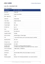
Diagram
Pin
Definition
Core Color
Description
1
Line0+
green
Opto-isolated input +
2
GND
blue
PWR GND & GPIO GND
3
Line0-
grey
Opto-isolated input -
4
POWER_IN
purple
Camera external power
(+12V DC)
5
Line2
orange
GPIO input/output
6
Line3
pink
GPIO input/output
7
Line1-
white green
Opto-isolated output -
8
Line1+
white blue
Opto-isolated
Table 7-2 I/O port definition (back sight of camera)
The input power of MER-G-P/MER-G series digital camera must be +12V (±10%) when powered by I/O
port.
The polarity of power cannot be reversed, otherwise, camera or other peripherals could burn out.
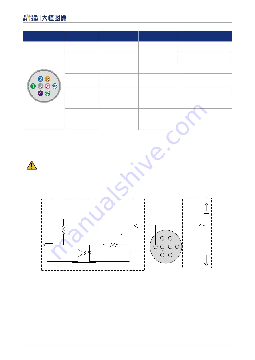
7.3.1.
Line0 (Opto-isolated Input) Circuit
Hardware schematics of opto-isolated input circuit is shown as Figure 7-1.
8
5
1
4
3
7
2
6
3.3V
Line0+
Line0-
INPUT0
External
Circuit
5V-24V
Camera internal circuit
Figure 7-1 Opto-isolated input circuit
Logic 0 input voltage: 0V~+2.5V (Line0+ voltage)
Logic 1 input voltage: +5V~+24V (Line0+ voltage)
Minimum input current: 7mA
The status is unstable when input voltage is between 2.5V and 5V, which should be avoided