


8.Features
© China Daheng Group, Inc. Beijing Image Vision Technology Branch 52
When the pixel format is set to Mono8, the brightness value of each pixel is 8 bits. The format in the
memory is as follows:
Y00
Y01
Y02
Y03
Y04
……
Y10
Y11
Y12
Y13
Y14
……
……
Among them Y00, Y01, Y02 … are the gray value of each pixel that starts from the first
row of the image.
Then the gray value of the second row pixels of the images is Y10, Y11, and Y12…
Mono10/Mono12
When the pixel format is set to mono10 or Mono12, each pixel is 16 bits. When Mono10 is selected, the
effective data is only 10 bits, the six unused most significant bits are filled with zero. When Mono12 is
selected, the effective data is only 12 bits, the 4 of the MSB 16 bits data are set to zero. Note that the
brightness value of each pixel contains two bytes, arranged in little-endian mode. The format is as follows:
Y00
Y01
Y02
Y03
Y04
……
Y10
Y11
Y12
Y13
Y14
……
……
Among them Y00, Y01, Y02…are the gray value of each pixel that start with the first
row of the image. The
first byte of each pixel is low 8 bits of brightness, and the second byte of each pixel is high 8 bits of
brightness.
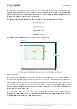
BayerRG8
When the pixel format is set to BayerRG8, the value of each pixel in the output image of the camera is 8
bits. According to the location difference, the three components of red, green and blue are respectively
represented. The format in the memory is as follows:


