
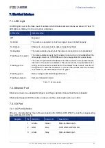

7.Electrical Interface
© 2023 China Daheng Group, Inc. Beijing Image Vision Technology Branch 51
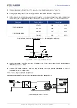
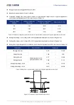
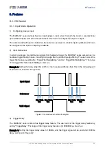
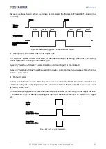
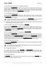
Delay time (td): the response time from OUTPUT1 rises to 50% of amplitude to LINE1+ decreases to
90% of amplitude
Falling time (tf): the response time for LINE1+ to decrease from 90% of the amplitude to 10%
Storage time (ts): the response time from OUTPUT1 decreases to 50% of amplitude to LINE1+ rises
to 10% of amplitude
Rising time (tr): the response time for LINE1+ to rise from 10% of the amplitude to 90%
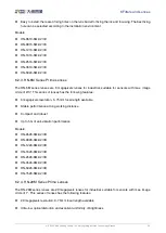
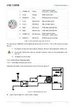
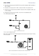
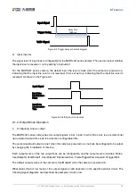
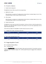
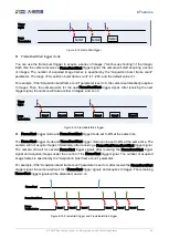
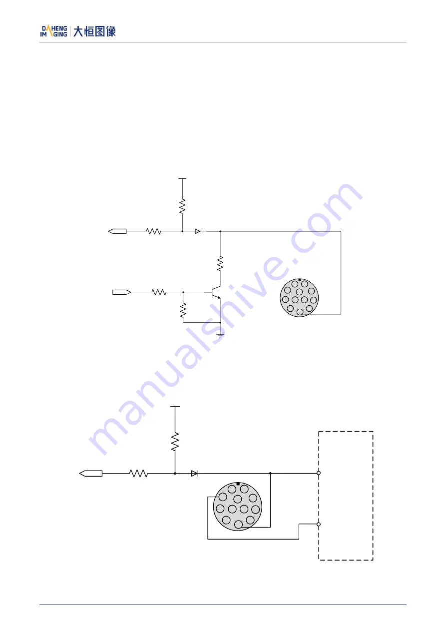
7.3.2.3.
GPIO 2 (Bidirectional) Circuit
9
1
2
3
4
5
6
7
8
12
11
10
3.3V
Line2
INPUT2
OUTPUT2
PTC
Figure 7-7 GPIO 2 (bidirectional) circuit
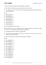
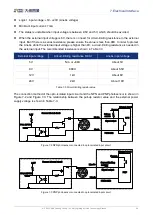
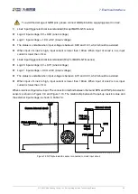
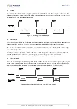
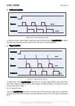
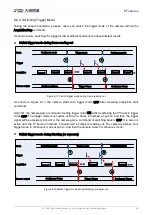
7.3.2.3.1.
Line2 is Configured as Input
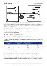
When Line2 is configured as input, the internal equivalent circuit of camera is shown in Figure 7-8, taking
Line2 as an example:
3.3V
Line 2
INPUT 2
9
1
2
3
4
5
6
7
8
12
11
10
Input -
Input +
External
circuit
Figure 7-8 Internal equivalent circuit of camera when Line2 is configured as input