background image


8.Features


©  2023 China Daheng Group, Inc. Beijing Image Vision Technology Branch                                                              106 

depends on the current image and cannot exceed the current image range. Assuming the current image 
width is Width, the image height is Height, then the ROI setting need to meet the following condition 2: 

AWBR AWBROIOffsetX≤Width 

AWBRO AWBROIOffsetY≤Height 

If condition 2 is not met, the user cannot set the ROI. 

The default value of ROI is the entire image, you can set the "white dot" area (ROI) according to your need. 
Where the minimum value of AWBROIWidth can be set is 16, the maximum value is equal to the current 
image width. The minimum value of AWBROIHeight can be set is 16, the maximum value is equal to the 
current image height, they are all need to meet the condition 2. 

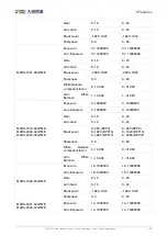
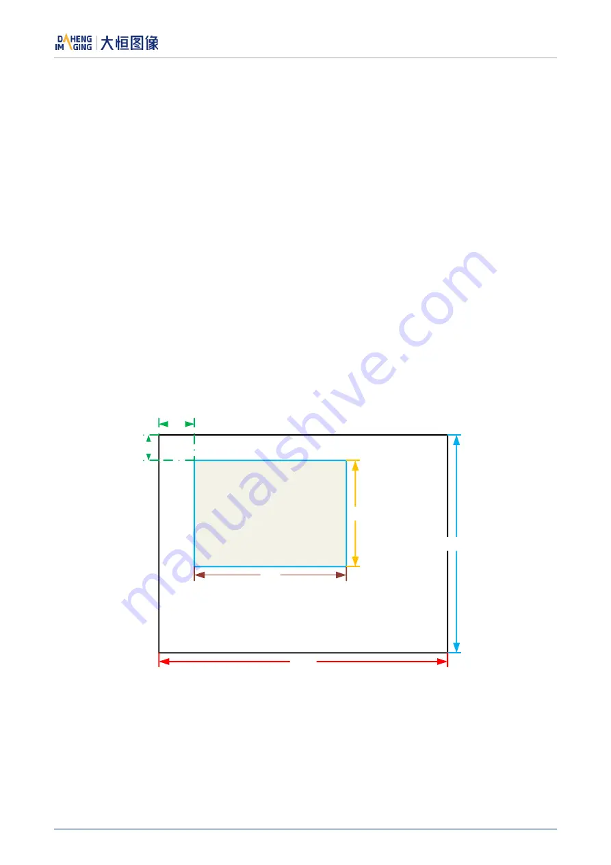
Assuming the current image width is 1024, the height is 1000, and then the "white dot" area ROI setting is: 

AWBROIOffsetX

100 

AWBROIOffsetY

50 

AWBROIWidth

640 

AWBROIHeight

480 

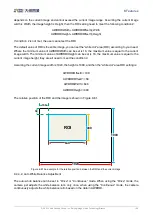
The relative position of the ROI and the image is shown in Figure 8-61. 

ROI

1024

1000

ROI

640

480

100

50


Figure 8-61 An example for the relative position between the ROI and the current image 

8.4.4.2.


Auto White Balance Adjustment 

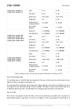
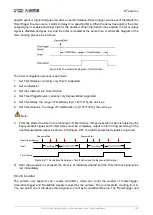
The auto white balance can be set to "Once" or "Continuous" mode. When using the "Once" mode, the 
camera just adjusts the white balance ratio only once, when using the "Continuous" mode, the camera 
continuously adjusts the white balance ratio based on the data in AWBROI. 

Содержание MARS 10GigE Series

Страница 1: ...MARS 10GigE Cameras User Manual Version V1 0 8 Date 2023 10 19 China Daheng Group Inc Beijing Image Vision Technology Branch...

Страница 2: ...anch The right is also reserved to modify or change any parts of this manual in the future without prior notification All other trademarks are the properties of their respective owners 2023 China Dahe...

Страница 3: ...on high transmission bandwidth and extremely low noise The camera is equipped with 10GigE interface which is backward compatible with GigE network cards The MARS family cameras are especially suitable...

Страница 4: ...3 Installation Guidelines 6 3 1 Host Preparation 6 3 1 1 Software Package 6 3 1 2 User Software Interface 6 3 2 Camera Power 8 3 3 Camera Driver Installation 8 3 3 1 System Requirements 8 3 3 2 Driver...

Страница 5: ...HN 20M Series Prime Lenses 42 6 2 5 HN P 6M Series Prime Lenses 43 6 2 6 HN P 10M Series Prime Lenses 44 6 2 7 HN P 20M Series Prime Lenses 44 6 2 8 HN P 25M Series Prime Lenses 44 6 2 9 HN P Series...

Страница 6: ...11 3 Set Exposure Time 75 8 2 11 4 Set Value of Exposure Time 75 8 2 12 Exposure Delay 75 8 3 Table Basic Features 78 8 3 1 Gain 78 8 3 2 Sensor Bit Depth 79 8 3 3 PGA Gain 79 8 3 4 Pixel Format 79 8...

Страница 7: ...8 5 Image Transmission 116 8 5 1 Maximum Allowable Frame Rate 116 8 5 2 Stream Channel Packet Size 122 8 5 3 Stream Channel Packet Delay 122 8 5 4 Bandwidth Reserve 123 8 6 Events 123 8 6 1 ExposureEn...

Страница 8: ...2023 China Daheng Group Inc Beijing Image Vision Technology Branch V 12 1 Contact Sales 139 12 2 Contact Support 139...

Страница 9: ...onnectors the MARS series cameras can secure the reliability of cameras deployed in harsh industrial environments Featuring high reliability and high price performance ratio the MARS series cameras ar...

Страница 10: ...camera in a limited volume and makes the camera highly reliable and environmentally adaptable Currently PCs generally do not support 10GigE transmission interfaces so users need to purchase 10GigE net...

Страница 11: ...ing 1 Do not install and operate the product in extreme environments with vibration high temperature humidity dust strong magnetic fields explosive corrosive smoke or gases as it may damage the camera...

Страница 12: ...to avoid earth loop 3 Try to use camera cables that are the correct length Avoid coiling camera cables If the cables are too long use a meandering path rather than coiling the cables 4 Keep your came...

Страница 13: ...30 EU Electromagnetic Compatibility Restriction 2011 65 EU Restriction of Hazardous Substances RoHS and its revised directive 2015 863 EU 2 FCC This device complies with Part 15 of the FCC Rules Opera...

Страница 14: ...IP address and to set the IP mode when the camera is powered on 5 Sample These samples demonstrate cameras functions the user can easily use these samples to control cameras or refer to the samples t...

Страница 15: ...Vision protocol In addition the user can use some third party software that supports the GigE Vision protocol to control the camera such as HALCON Note GEN i CAM standard GEN i CAM is administered by...

Страница 16: ...ows Windows 10 32bit 64bit Windows 11 64bit Windows 10 64 bit system is recommended for MARS GT series cameras please contact our technical support under other systems 3 3 2 Driver Installation The st...

Страница 17: ...of the installation package 3 Click Auto Configure IP on the right side of the GigE IP Configurator to automatically configure the IP Figure 3 2 GigE IP Configurator 3 5 Open Device and Start Acquisi...

Страница 18: ...ology Branch 10 1 Click the icon on the Device Tree in the GalaxyView to refresh device list 2 After the device is enumerated double click the device enumerated in the device list 3 Click the icon on...

Страница 19: ...aphs ordinate is relative sensitivity response and abscissa is wavelength Some graphs ordinate is QE and abscissa is wavelength 4 2 MARS 561 207GTM C Specifications MARS 561 207GTC MARS 561 207GTM Res...

Страница 20: ...in11 32bit 64bit OS 64bit OS is recommended Programmable Control Image size gain exposure time trigger polarity flash polarity Conformity CE FCC RoHS GigE Vision GenICam 1 Monochrome camera As shown b...

Страница 21: ...Figure 4 3 MARS 561 207GTC clusters within different Bayer color plane distribution diagram Figure 4 4 MARS 561 207GTM C sensor spectral response 4 3 MARS 900 120GTM C Specifications MARS 900 120GTC...

Страница 22: ...t with opto isolated 1 bidirectional programmable GPIO Operating Temp 0 C 50 C Storage Temp 20 C 70 C Operating Humidity 10 80 Camera Power Requirements 12VDC 10 24VDC 10 Power Consumption 12 7W 24VDC...

Страница 23: ...ignal Noise Ratio 39 95dB 39 93dB Exposure Time Ultra short 15 s 36 s Actual Steps 1 s Standard 37 s 1s Actual Steps 1 row period Gain 0dB 24dB Default 0dB Step 0 1dB Binning 1 1 2 1 No vertical Binni...

Страница 24: ...RoHS GigE Vision GenICam Figure 4 5 MARS 1261 90GTM C sensor spectral response 4 5 MARS 1610 52GTM C Specifications MARS 1610 52GTC MARS 1610 52GTM Resolution 5328 3040 Sensor Type Sony IMX542 Global...

Страница 25: ...utput with opto isolated 1 bidirectional programmable GPIO Operating Temp 0 C 50 C Storage Temp 20 C 70 C Operating Humidity 10 80 Camera Power Requirements 12VDC 10 24VDC 10 Power Consumption 12 8W 2...

Страница 26: ...gnal Noise Ratio 37 59dB 37 2dB Exposure Time 10 s 1s Actual Steps 1 row period Gain 0dB 16dB Default 0dB Step 0 1dB Binning 1 1 2 1 No vertical Binning Decimation Horizontal FPGA Vertical Sensor 1 1...

Страница 27: ...tion diagram refer to 4 2 section Figure 4 7 MARS 1840 63GTM C sensor spectral response 4 7 MARS 2020 42GTM C Specifications MARS 2020 42GTC MARS 2020 42GTM Resolution 4512 4512 Sensor Type Sony IMX54...

Страница 28: ...Temp 20 C 70 C Operating Humidity 10 80 Camera Power Requirements 12VDC 10 24VDC 10 Power Consumption 12 8W 24VDC Lens Mount C Data Interface Gigabit Ethernet 1000Mbit s or 10G Ethernet 10000Mbit s Di...

Страница 29: ...inning 1 1 2 1 No vertical Binning Decimation Sensor 1 1 2 2 Synchronization Hardware trigger software trigger I O 1 input and 1 output with opto isolated 1 bidirectional programmable GPIO Operating T...

Страница 30: ...t Mono Color Color Mono Pixel Formats Bayer GB8 Bayer GB12 Mono8 Mono12 Signal Noise Ratio 35 24dB 35 54dB Exposure Time 14 s 1s Actual Steps 1 row period Gain 0dB 16dB Default 0dB Step 0 1dB Binning...

Страница 31: ...grade of the sensor The difference between Grade1 and Grade2 sensors defined by sensor manufacturers is Grade1 have no consecutive defect pixel cluster and Grade2 may have up to 12 consecutive defect...

Страница 32: ...tion Synchronization Hardware trigger software trigger I O 1 input and 1 output with opto isolated 1 bidirectional programmable GPIO Operating Temp 0 C 50 C Storage Temp 20 C 70 C Operating Humidity 1...

Страница 33: ...tribution diagram refer to 4 2 section The sensor spectral response refer to 4 9 section 4 11 MARS 2621 42GTM C S MARS 2622 42GTM C S Specifications MARS 2621 42GTC S MARS 2622 42GTC S MARS 2621 42GTM...

Страница 34: ...mable Control Image size gain exposure time trigger polarity flash polarity Conformity CE FCC RoHS GigE Vision GenICam The camera s cluster distribution diagram refer to 4 2 section The sensor spectra...

Страница 35: ...le from 0 to 8 vertically Data Interface Gigabit Ethernet 1000Mbit s or 10G Ethernet 10000Mbit s Dimensions 40mm 70mm 76 05mm without lens adapter or connectors Weight 288g Operating System Win10 Win1...

Страница 36: ...are trigger I O 1 input and 1 output with opto isolated 1 bidirectional programmable GPIO Operating Temp 0 C 50 C Storage Temp 20 C 70 C Operating Humidity 10 80 Camera Power Requirements 12VDC 10 24V...

Страница 37: ...ples 1 Maximum cluster size within same Bayer color plane is 4 but cluster with 4 consecutive defect pixels in a row is not allowed Figure 4 10 MARS 5000 24GTC MARS 5000 24GTC NF clusters within same...

Страница 38: ...Bayer GB12 Mono8 Mono12 Signal Noise Ratio 40 42dB 40 05dB Exposure Time 14 s 1s Actual Steps 1 row period Gain 0dB 16dB Default 0dB Step 0 1dB Binning 1 1 1 2 2 1 2 2 Decimation Horizontal FPGA Verti...

Страница 39: ...difference between the two cameras is the grade of the sensor The difference between Grade1 and Grade2 sensors defined by sensor manufacturers is Grade1 have no consecutive defect pixel cluster and Gr...

Страница 40: ...C MARS 1840 630GTM C MARS 2020 42GTM C MARS 2440 35GTM C MARS 2621 42GTM C MARS 2622 42GTM C MARS 2621 42GTM NIR MARS 2622 42GTM NIR C No active cooling A MARS 2621 42GTM C S MARS 2622 42GTM C S MARS...

Страница 41: ...5 Dimensions 2023 China Daheng Group Inc Beijing Image Vision Technology Branch 33 Figure 5 2 MARS GT mechanical dimensions B Figure 5 3 MARS GT mechanical dimensions C...

Страница 42: ...5 Dimensions 2023 China Daheng Group Inc Beijing Image Vision Technology Branch 34 Figure 5 4 MARS GT mechanical dimensions D Figure 5 5 MARS GT mechanical dimensions E...

Страница 43: ...5 Dimensions 2023 China Daheng Group Inc Beijing Image Vision Technology Branch 35 Figure 5 6 MARS GT mechanical dimensions F Figure 5 7 MARS GT mechanical dimensions G...

Страница 44: ...rt on the image The filter substrate has an impact on the rear focus and removing it may cause unclear focus If it must be removed please contact our technical support Models Mount Flange Distance in...

Страница 45: ...ew specification tripod adapter step thickness and spring washer thickness 2 It is recommended that you select the screw specifications and the tripod adapter step thickness from the table below A Cam...

Страница 46: ...pecification Tripod adapter step thickness mm Spring washer thickness mm Screwing length of camera screw thread mm M4 8 screw 3 5 1 3 5 M4 10 screw 5 5 1 3 5 If the screw specification and the thickne...

Страница 47: ...e cut off frequency is 700nm which reduces the influence of invisible light on the image The monochrome models are equipped with transparent glasses Remove IR filters or transparent glasses will defoc...

Страница 48: ...maximum sensor size that the lens image can cover There are mainly 1 2 2 3 1 1 2 1 1 1 4 3 and so on When selecting a lens make sure that the lens max image circle is not smaller than the sensor size...

Страница 49: ...with a unique mechanical structure the optical axis fluctuates below 10 m The housing is small and compact the minimum outer diameter is only 29 5mm and it can be installed in various limited spaces...

Страница 50: ...sors with max image circle of 2 3 This series of lenses has the following features 6 megapixels resolution 5 75mm focal length available Stable performance at long working distance Compact and robust...

Страница 51: ...5 HN P 6M Series Prime Lenses The HN P 6M series lenses are 6 megapixels lenses for industrial suitable for sensors with max image circle of 1 1 8 2 3 This series of lenses has the following features...

Страница 52: ...P 0824 10M C2 3 HN P 1220 10M C2 3 HN P 1618 10M C2 3 HN P 2518 10M C2 3 HN P 3520 10M C2 3 HN P 5028 10M C2 3 6 2 7 HN P 20M Series Prime Lenses The HN P 20M series lenses are 20 megapixels lenses fo...

Страница 53: ...erture design Small and compact Ultra low optical distortion Models HN P 1224 25M C1 2 1 HN P 1624 25M C1 2 1 HN P 2524 25M C1 2 1 HN P 3524 25M C1 2 1 HN P 5024 25M C1 2 1 6 2 9 HN P Series 8K 16K Li...

Страница 54: ...manent IP address and other real time save parameters are incorrect or the camera is started in the userset mode the parameter set is wrong and the camera is switched to the default mode to start Use...

Страница 55: ...Table 7 2 I O port definition back sight of camera The input power of MARS GT series digital camera must be 12V 10 24V 10 when powered by I O port 1 The polarity of power cannot be reversed otherwise...

Страница 56: ...Circuit limiting resistance Rlimit Line0 input voltage 5V Non or 90 About 5V 9V 680 About 5 5V 12V 1k About 6V 24V 2k About 10V Table 7 3 Circuit limiting resistor value The connection method of the...

Страница 57: ...2 46 5 14 Falling edge delay VIN 5V 6 12 17 71 VIN 12V 8 93 19 73 Table 7 4 Delay time of opto isolated input circuit in typical application environment TRIGIN _F_DELAY TRIGIN_R_DELAY 2V 0 8V LINE0 I...

Страница 58: ...isolated output circuit in typical application environment Rising time delay tr ts 50 s 0 C 45 C parameter description is shown in Figure 7 6 Falling time delay ts tf 50 s 0 C 45 C parameter descripti...

Страница 59: ...INE1 rises to 10 of amplitude Rising time tr the response time for LINE1 to rise from 10 of the amplitude to 90 7 3 2 3 GPIO 2 Bidirectional Circuit 9 1 2 3 4 5 6 7 8 12 11 10 3 3V Line2 INPUT2 OUTPUT...

Страница 60: ...andard Only for MARS GT S series Logic 0 input voltage 0V 0 7V Line2 voltage Logic 1 input voltage 3 3V 24V Line2 voltage The status is unstable when input voltage is between 0 7V and 3 3V which shoul...

Страница 61: ...own in Figure 7 4 7 3 2 3 2 Line2 is Configured as Output Range of external voltage EXVCC is 5 24V Maximum output current of Line2 is 25mA output impedance is 40 Transistor voltage drop and output cur...

Страница 62: ...time tf 1 82 1 94 Rising time delay tf td 0 19 0 26 Falling time delay tr ts 1 97 2 09 Table 7 8 Delay time when GPIO is configured as output in typical conditions When Line2 is configured as output...

Страница 63: ...including rising edge filtering and falling edge filtering The user can set the trigger filter feature by setting the TriggerFilterRaisingEdge and the TriggerFilterFallingEdge The range of the trigge...

Страница 64: ...ineInverter True Figure 8 3 Setting input line reverse 8 1 2 Output Mode Operation 1 Configuring Line as output The MARS GT series camera has two output signals Line1 Line2 In which the Line1 is a uni...

Страница 65: ...tant light source or the alarm light two level types are available high level or low level For example select Line2 as the output line the output source is selected as UserOutput1 and the output value...

Страница 66: ...gger please use the AcquisitionStatus When the camera is ready to receive a trigger signal of the corresponding trigger mode the TriggerWait signal goes low When the corresponding trigger signal is us...

Страница 67: ...erOutputSelector to select UserOutput0 UserOutput1 or UserOutput2 By setting UserOutputValue to set the user defined output value and the default value is false when the camera is powered on 3 Output...

Страница 68: ...MARS GT series camera can get the current status of all lines On the one hand the signal status is the status of the external I O after the reversal of the polarity On the other hand signal status lev...

Страница 69: ...Acquisition Exposure Reading out Start Status Trigger Figure 8 11 Trigger acquisition process In trigger mode sending AcquisitionStart command is not enough a trigger signal is also needed Each time...

Страница 70: ...rded Acquisition stop during blanking Complete stop Reading out Stop command Stop time Exposure Ignored Figure 8 13 Acquisition stop during blanking After the camera transferred a whole frame the came...

Страница 71: ...e the camera receives a trigger signal it can acquire a frame of image until the AcquisitionStop command is executed It is not necessary to execute the AcquisitionStart command every time 2 When the t...

Страница 72: ...Trigger Signal frame2 frame2 frame1 frame3 frame5 frame4 frame6 Figure 8 15 FrameBurstStart trigger FrameStart trigger mode and FrameBurstStart trigger mode set to ON at the same time The FrameStart...

Страница 73: ...with trigger mode OFF after receiving acquisition start command At point 1 the camera gets a command of setting trigger mode ON while transferring the 3rd frame in trigger mode OFF The trigger mode i...

Страница 74: ...Other parameters also can be changed in Trigger Mode OFF Continuous mode features In continuous acquisition mode the camera acquires and transfers images according to camera parameter set In continuo...

Страница 75: ...er signal This camera can support separate setting of raising edge filter and falling edge filter The default configuration is not use trigger filter 3 Trigger delay whether to generate image frame af...

Страница 76: ...gerActivation choose RisingEdge or FallingEdge manually 2 TriggerFilter whether to filter the hardware trigger signal Filter function is not available for software trigger MARS GT camera support Risin...

Страница 77: ...r waiting signal is detected Generally the cached trigger signals will trigger the sensor according to the sensor read limit frame cycle However when the frame rate control is effective and the frame...

Страница 78: ...r Trigger Trigger Figure 8 20 The trigger acquisition exposure sequence diagram in non overlap exposure mode Overlap exposure In overlap exposure mode the current frame image exposure process is overl...

Страница 79: ...Exposure 8 2 11 1 Set Exposure Mode Two Exposure Mode are available Timed exposure mode and TriggerWidth exposure mode Among them the TriggerWidth exposure mode determines the exposure time when the c...

Страница 80: ...erwise the trigger signal will be ignored and a FrameStartOvertrigger event will be generated b TriggerWidth exposure mode In TriggerWidth exposure mode the length of exposure is determined by the wid...

Страница 81: ...e hardware trigger sources e g Line0 c Set the ExposureMode parameter to TriggerWidth if available 8 2 11 2 Set Sensor Exposure Mode Global Shutter The implementation process of global shutter is as s...

Страница 82: ...e time Readout time All lines are exposuring at the same time Readout after exposure Reading Time Exposing Figure 8 29 Global Reset Release shutter The implementation process of electronic rolling shu...

Страница 83: ...The MARS GT series camera supports setting the exposure time step 1 s The exposure precision of the camera is limited by the sensor when the steps in the user s interface and the demo display as 1 s...

Страница 84: ...emperature When the external environment is constant the delay is generally stable T2 Delay introduced by the trigger filter For example if the trigger filter time is set to 50 s T2 is 50 s T3 Trigger...

Страница 85: ...82 s Overlap Exposure When pixel format is BayerRG8 Mono8 19706 s When pixel format is BayerRG12 Mono12 34082 s MARS 1610 52GTM C MARS 2440 35GTM C When Decimation is Off When pixel format is BayerGB8...

Страница 86: ...5 s 37205 s Table 8 2 MARS GT series camera exposure delay range 8 3 Table Basic Features 8 3 1 Gain The MARS GT series camera can adjust the analog gain the adjustable range of every model refer to 4...

Страница 87: ...se caused by ADC so it has a smaller impact on SNR The steps set by the user is different from the actual steps For example the PGA gain of the MARS 5000 24GTM C camera in the remove standard paramete...

Страница 88: ...els of the images is Y10 Y11 and Y12 Mono12 When the pixel format is set to Mono12 each pixel is 16 bits When Mono12 is selected the effective data is only 12 bits the 4 of the MSB 16 bits data are se...

Страница 89: ...row pixel values are arranged G10 is the first pixel value of the second row for the green component the B11 is the second pixel value for the blue component and so on and the second row of pixel valu...

Страница 90: ...row pixel values are arranged B10 is the first pixel value of the second row for the blue component the G11 is the second pixel value for the green component and so on and the second row of pixel valu...

Страница 91: ...ues in the first row R10 represents the first pixel value red component in the second row G11 represents the second pixel value green component and so on completing the arrangement of pixel values in...

Страница 92: ...f the ROI of the image are defined the 0th line and 0th columns as the origin of the upper left corner of the sensor As shown in the figure the OffsetX of the ROI is 4 the OffsetY is 4 the height is 8...

Страница 93: ...nd the maximum value is equal to the current image width The minimum value of AAROIHeight can be set to 16 and the maximum value is equal to the current image height they are all need to meet the cond...

Страница 94: ...camera will continuous adjusting the exposure time according to the data of the AAROI so that the data in the ROI is kept near to the expected gray level The expected gray value is set by the user an...

Страница 95: ...he image is scrolling to the left A printscreen of the moving diagonal gray gradient test image is shown in Figure 8 35 Image rolling direction Image rolling direction Figure 8 35 Moving diagonal gray...

Страница 96: ...rs Default or the user configuration parameters UserSet to the current effective configuration parameters The UserSetDefault is refer to the user can specify a set of parameters which to be loaded int...

Страница 97: ...ters 2 The operation of configuration parameters The operations for configuration parameters include the following three types save parameters load parameters and set the UserSetDefault Save parameter...

Страница 98: ...UserSet0 2 Execute UserSetLoad command to load the User Set specified by UserSetSelector to the device and makes it active Change startup parameter set UserSetDefault The user can use UserSetDefault...

Страница 99: ...equency of timestamp counter is obtained by reading the camera s timestamp tick frequency The unit is 1ns Timestamp latch Latch the current timestamp value The timestamp value needs to be read through...

Страница 100: ...ectly adjacent pixels Figure 8 41 Horizontal mono Binning by 4 Binning Factors Two types of Binning are available horizontal Binning and vertical Binning You can set the Binning factor in one or two d...

Страница 101: ...ase you can reduce the lens aperture the intensity of your illumination the camera s exposure time setting or the camera s gain setting 3 Possible image distortion Objects will only appear undistorted...

Страница 102: ...ses the camera s frame rate How Horizontal Decimation Works On mono cameras if you specify a horizontal Decimation factor of n the camera transmits only every nth column For example if specify set a h...

Страница 103: ...abled the effective resolution of the sensor is restored to 5120 5120 2 Simultaneous horizontal Decimation and vertical Decimation settings Horizontal Decimation and vertical Decimation cannot be set...

Страница 104: ...Reverse Y set the ReverseY parameter to true The camera mirrors the image vertically Figure 8 48 The original image Figure 8 49 Reverse Y enabled Enabling Reverse X and Y To enable Reverse X and Y set...

Страница 105: ...t Works Configuring a digital shift factor of n results in a logical left shift by n on all pixel values This has the effect of multiplying all pixel values by 2n If the resulting pixel value is great...

Страница 106: ...bit pixel format In this case the camera first performs the digital shift calculation on the 12 bit image data Then the camera transmits the 8 most significant bits Example 3 Digital Shift by 1 12 bi...

Страница 107: ...k level value can only be selected as all pixels and pixel selection is not supported The lower the black level the darker the corresponding image the higher the black level the brighter the correspon...

Страница 108: ...8 MARS 1610 52GTM C MARS 2020 42GTM C MARS 2440 35GTM C Exposure 3 1000000 3 15000000 Auto Exposure 3 1000000 3 15000000 Gain 0 16 0 24 Auto Gain 0 16 0 24 Black Level 0 255 BPP8 0 1023 BPP10 0 4095 B...

Страница 109: ...el 1023 1024 1023 1024 Sharpness 0 3 0 63 White Balance component factor 0 15 998 0 31 998 Auto White Balance 1 15 998 1 31 998 Table 8 3 Parameter range of features supported before and after Remove...

Страница 110: ...the range of TimerDelay is 0 16777215 the unit is s 6 Set TimerDuration the range of TimerDuration is 0 16777215 the unit is s Note 1 From the start of the timer to the full output of Timer1Active th...

Страница 111: ...art FrameTrigger AcquisitionTrigger 3 Set CounterResetSource the values that can be set are Off SoftWare Line0 Line2 4 Set CounterResetActivation currently only RisingEdge supported 1 After the acquis...

Страница 112: ...fference value is greater than the threshold it is determined as noise Static defect pixel correction requires a new image click auto tagging to obtain the coordinates of the noise defect pixels When...

Страница 113: ...he external environment light source used is D65 light source the image will not produce color deviation Even if the current light source is selected as the light source preset users can also manually...

Страница 114: ...dth The minimum value of AWBROIHeight can be set is 16 the maximum value is equal to the current image height they are all need to meet the condition 2 Assuming the current image width is 1024 the hei...

Страница 115: ...ot this color template with a camera the RGB value of each color may be different from the standard RGB value of the standard color template the vendor can use the software or hardware to convert the...

Страница 116: ...sformation value according to the actual situation to achieve the color transformation effect 3 How it works The color transformation feature uses a transformation matrix to deliver modified red green...

Страница 117: ...e form of a matrix so the saturation is adjusted at the same time after color correction is enabled 4 Effect images Figure 8 65 Before saturation Figure 8 66 After saturation 8 4 7 Gamma The Gamma can...

Страница 118: ...nding on your camera model the following additional parameters are available a GammaEnable Enables or disables Gamma correction b GammaMode You can select one of the following Gamma correction modes U...

Страница 119: ...nconsistency of the image As shown below the FFC can adjust the pixel values of different positions to the same gray value Figure 8 69 Before FFC Figure 8 70 After FFC The flat field correction functi...

Страница 120: ...C coefficient is obtained it is recommended to determine the aperture of the lens and the gain of the camera In the following cases the coefficient needs to be re calculated Lens is replaced If the re...

Страница 121: ...g the acquired images After execution the subsequent images automatically use the calculated coefficients for FFC 4 Preview Preview the effect of the current FFC 8 4 9 1 2 Read Save Coefficient Read c...

Страница 122: ...camera gain before calculating FFC coefficient In the following cases the coefficient need to be repeated Lens replacement When there is a high requirement for FFC coefficient accuracy eg correct the...

Страница 123: ...ng them in the camera to avoid time consuming calculations The camera itself has a factory default lookup table and the default lookup tables do not affect image luminance 2 Creating the user defined...

Страница 124: ...rate of the network is the camera s maximum transmission frame rate that the current network supports The maximum frame rate that the MARS GT series camera network supports is determined by the camera...

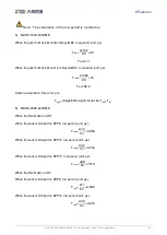
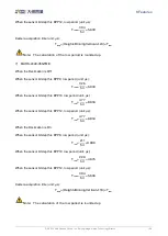
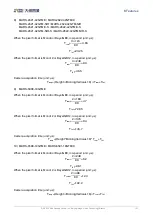
Страница 125: ...as follows 1 MARS 561 207GTM C When the pixel format is Mono8 or BayerGB8 row period unit s Trow 1 176 80 2 2 Tfot 22 0 When the pixel format is Mono10 or BayerGB10 row period unit s Trow 1 352 80 4...

Страница 126: ...ff When the sensor bit depth is BPP8 row period unit s Trow 326 54 6 038 When the sensor bit depth is BPP10 row period unit s Trow 477 54 8 834 When the sensor bit depth is BPP12 row period unit s Tro...

Страница 127: ...80 7 6 Tfot 102 6 Camera acquisition time unit s Tacq Height BinningVertical 16 Trow Tfot 6 MARS 2020 42GTM C When the Decimation is Off When the sensor bit depth is BPP8 row period unit s Trow 273 5...

Страница 128: ...is BPP8 row period unit s Trow 326 54 6 038 When the sensor bit depth is BPP10 row period unit s Trow 477 54 8 834 When the sensor bit depth is BPP12 row period unit s Trow 477 54 8 834 When the Deci...

Страница 129: ...acquisition time unit s Tacq Height BinningVertical 16 Trow Tfot 9 MARS 5000 18GTM C When the pixel format is Mono8 or BayerGB8 row period unit s Trow 2 188 80 4 7 Tfot 72 85 When the pixel format is...

Страница 130: ...more than 1500 bytes it needs the network equipment such as network card and switch to support the jumbo frames 2 When changing the packet size the packet size and the packet delay will affect the ne...

Страница 131: ...a part of bandwidth for packet retransmission and control data transfer between the camera and the host and can be used for multiple cameras transmission to limit the bandwidth allocation of each cam...

Страница 132: ...at the camera sends does not receive the reply packet the camera will retransmit the event according to the retransmission timeout and retransmission times The effective information contained in each...

Страница 133: ...t this time if the EventOverrun event is enable the camera will send an EventOverrun event to the host and discard all the events in the current cache 8 6 4 FrameStartOvertrigger Event When the camera...

Страница 134: ...in Figure 8 75 Sequencer0 Exposure time 10ms Gain 1dB Sequencer0 Exposure time 1ms Gain 16dB SequencerN 1 Exposure time 60ms Gain 8dB Figure 8 75 Sequencer feature schematic diagram 8 7 1 Features Se...

Страница 135: ...is supported SequencerSetSelector is set to N and then SequencerSetNext can only be set to N 1 or 0 and the maximum value of N 1 is the maximum number of sequence sets supported 1 If the maximum numb...

Страница 136: ...440 35GTM C MARS 2621 42GTM C MARS 2622 42GTM C MARS 2621 42GTM NIR MARS 2622 42GTM NIR MARS 2621 42GTM C S MARS 2622 42GTM C S MARS 2621 42GTM NIR S MARS 2622 42GTM NIR S 4 ExposureTime Gain Gamma MA...

Страница 137: ...as Figure 9 2 Figure 9 2 GxGigEIPConfig interface The left side of the interface is device list showing all searched GigE Gigabit Ethernet 1 When GigE is selected all GigE cameras will be shown in th...

Страница 138: ...ify IP Address will be forbidden 1 Release Occupation 2 Reset Device Occupy When the camera is opened in Exclusive mode by other processes By this time the Auto Configure IP and Modify IP Address will...

Страница 139: ...row of the camera in the list the window as Figure 9 4 Figure 9 4 Modify IP Address The default setting is Static IP and in here users can set IP Address Subnet Mask and Gateway Note It is restrict to...

Страница 140: ...through routing Optional operation Modify Device User ID the maximum length of user defined name is 16 characters Release Occupation The camera heart beat time is 5min by default VS develop in debugg...

Страница 141: ...lows 1 The Width and Height are the set ROI size 2 The ExposureTime is the exposure time when the camera acquires one frame of image 3 The PixelFormat is the pixel format corresponding to the camera o...

Страница 142: ...tion of the camera into the corresponding table When the filled value exceeds the range or does not conform to the rules the calculation tool will report an error Please modify and fill in the value a...

Страница 143: ...Intel series 10 Gigabit network card or IOI series 10 Gigabit network card 3 Contact with the technical support 3 Lose frames seriously in a multiple cameras application 1 Adjust the packet size or p...

Страница 144: ...ing 5M the image can be successfully acquired It is not recommended to set the size of the data block to 1M or 2M This small data block operation may affect the stability of the system 3 Method 3 incr...

Страница 145: ...3 and Figure 5 4 4 Add section 8 3 3 PGA Gain and section 8 7 Sequencer 2023 05 23 4 V1 0 3 1 Update 8 2 12 section update the descriptions of exposure delay 2 Add 8 4 1 8 4 2 and 8 4 9 sections 3 Upd...

Страница 146: ...Add 8 8 Fan Control 7 V1 0 6 1 Add MARS 1261 90GTM C model and related information 2 Update the UI interface and usage description related to the software 2023 09 13 8 V1 0 7 1 Update section 2 5 sec...

Страница 147: ...ou need to order products or inquire product information please contact our sales Tel 86 10 8282 8878 8081 Email isupport daheng imaging com 12 2 Contact Support If you have any questions in using DAH...

Отзывы: