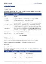

7.Electrical Interface
© 2023 China Daheng Group, Inc. Beijing Image Vision Technology Branch 52
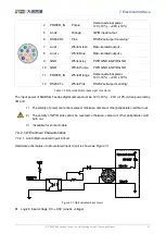
To avoid the damage of GPIO pins, please connect GND pin before supplying power to Line2.
1)
Line2 input trigger electrical level standard (Except MARS-GT-S series)
Logic 0 input voltage: 0V~+0.6V (Line2 voltage)
Logic 1 input voltage: +1.9V~+24V (Line2 voltage)
The status is unstable when input voltage is between 0.6V and 1.9V, which should be avoided
When input of Line2 is high, input current is lower than 100uA. When input of Line2 is low, input
current is lower than -1mA
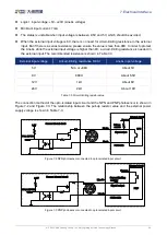
2)
Line2 input trigger electrical level standard (Only for MARS-GT-S series)
Logic 0 input voltage: 0V~+0.7V (Line2 voltage)
Logic 1 input voltage: +3.3V~+24V (Line2 voltage)
The status is unstable when input voltage is between 0.7V and 3.3V, which should be avoided
When input of Line2 is high, input current is lower than 100uA. When input of Line2 is low, input
current is lower than -1mA
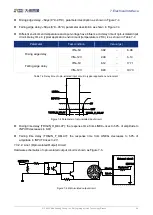
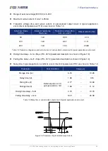
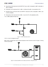
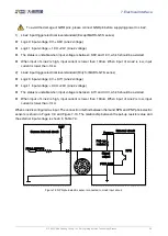
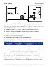
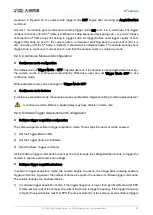
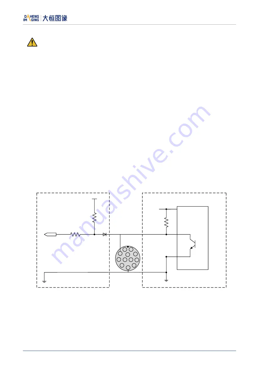
When Line2 is configured as input. The connection method between them and NPN and PNP photoelectric
sensors is shown in Figure 7-9 and Figure 7-10. The relationship between the pull-up resistor value and
the external input voltage is shown in Table 7-3.
3.3V
Line 2
FPGA INPUT2
Camera internal circuit
External circuit
Signal
output
Power +
PWR GND
NPN
Pull- up
resistor
9
1
2
3
4
5
6
7
8
12
11
10
Figure 7-9 NPN photoelectric sensor connected to Line2 input circuit