Daewoo XL-115 Скачать руководство пользователя страница 4

Safety Precautions

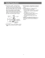
13.Outdoor Antenna Grounding - If an outside antenna


is 

connected to the receiver be sure the antenna


system is 

grounded so as to provide some protection against voltage 
surges and built-up static


charges. Article 810 of the National 

Electrical Code,


ANSI/NFPA 70, provides information with 

regard to


proper grounding of the mast and supporting


structure, grounding of the lead-in wire to an antenna-dis
charge unit, size of grounding conductors,location of antenna-
discharge unit, connection to grounding electrodes and 
requirements for the grounding electrode.  See Figure 1.

14.Non-use Periods - The power cord of the appliance should be 

unplugged from the outlet when left


unused for a long period 

of time.

15.Object and Liquid Entry - Care should be taken so


that objects 

do not fall and liquids are not spilled into the enclosure through 
openings. 

16.Damage Requiring Service - The appliance should


be 

serviced by qualified service personnel when:
  a) The power-supply cord or the plug has been


damaged; or

  b) Objects have fallen, or liquid has been spilled


into the

      appliance; or
  c) The appliance has been exposed to rain; or
  d) The appliance does not appear to operate


normally or 

      exhibits a marked change in


performance; or

  e) The appliance has been dropped, or the


enclosure 

      damaged.

 17.Servicing - The user should not attempt to service the 

appliance beyond that described in the operating instructions. 
All other servicing 


should be referred to qualified service 

personnel.

ANTENNA DISCHARGE UNIT

(NEC SECTION 810-20)

ANTENNA LEAD

IN WIRE

POWER SERVICE GROUNDING

ELECTRODE SYSTEM

(NEC ART 250 PART H)

GROUND CLAMP

ELECTRIC

SERVICE

EQUIPMENT

GROUNDING CONDUCTORS

(NEC SECTION 810-21)

GROUND CLAMPS

EXAMPLE OF ANTENNA 

GROUNDING 

NEC - NATIONAL ELECTRICAL CODE

- 3 -

Содержание XL-115

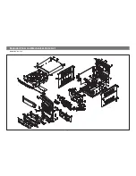
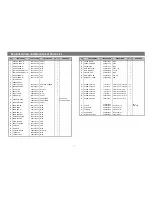
Страница 1: ...Service Manual MINI COMPONENT SYSTEM Model DAEWOO ELECTRONICS CO LTD XL 115...

Страница 2: ...PRECAUTIONS 2 ADJUSTMENTS 4 EXPLODED VIEW AND PARTS LIST 5 WIRING DIAGRAM 7 BLOCK DIAGRAM 8 SCHEMATIC DIAGRAM 9 POWER AMP TUNER TAPE 9 CD 10 CONTROL 11 PCB PATTERN LAYOUT 12 ELECTRICAL PART LIST 16 MI...

Страница 3: ...ld be used only with a cart or stand that is recommended by th manufacturer 3 An appliance and cart combination should be moved with care Quick stops excessive force and uneven surfaces may cause the...

Страница 4: ...at objects do not fall and liquids are not spilled into the enclosure through openings 16 Damage Requiring Service The appliance should be serviced by qualified service personnel when a The power supp...

Страница 5: ...25Hz MTT 111N RV601 Line Out L R Channel Confirm Wow Flut ter is within 0 35 FIG 1 3 000 3 010Hz MTT 111N RV601 Line Out L R Channel Confirm Tape Speed of end position after adjustment at tape start p...

Страница 6: ...7 25 27 35 P3 S2 S2 S2 S2 S2 S3 S3 S3 S3 S3 3 24 S3 S3 26 40 28 S6 S4 S4 S4 S2 P4 10 14 18 P5 37 P1 S1 S1 S1 S1 XL 115R 8 19 S2 P2 S7 36 36 S5 S5 S2 S2 39 38 5 S2 S2 S2 S2 S3 S3 S3 S3 S3 S5 15 S3 S3 S...

Страница 7: ...3 0 X 12 BK 19 14 BRKT SIDE 9CD2412900 MIPS 2 S4 SCREW TAPTTITE 7173301612 TT2 BIN 4 0 X 6 MFZN 4 15 PANEL FRONT 9CD0308200 MIPS 1 S5 SCREW TAPTTITE 7173400611 TT2 BIN 3 0 X 6 MFZN 5 16 WINDOW FLT 9C...

Страница 8: ...220MM FD701 CW508 IC702 CN703 CN704 CN701 SN 9738834000 11P 150MM SN 9738834100 13P 100MM 50W 30W CW900 SN 9728804100 10P 300MM W POWER SAVE MODE SN 9738833900 8P 300MM W O POWER SAVE MODE CN401 CN40...

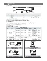
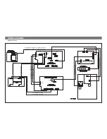
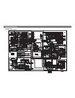
Страница 9: ...BLOCK DIAGRAM Model No XL 115 8...

Страница 10: ...N IFIN FM SD AMIN NC ST MO IF REQ LW S CURVE AM FM IF BUFF 304KHz 19K 19K 0 16 1 2 3 6 14 5 13 8 11 7 12 4 9 10 15 VDD1 R DATA QUAL R CLK CLOCK VSS1 ANALOG V REF VSS2 VSS3 PLL 1187 5Hz PLL 57KHz RDS A...

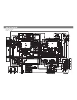
Страница 11: ...Schemetic Diagram Model No XL 115 Ass y Name CD 1 0...

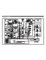
Страница 12: ...Schemetic Diagram Model No XL 115 Ass y Name Control 11...

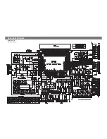
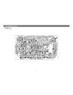
Страница 13: ...P C B Pattern Layout 12 Model No XL 115 Ass y Name MAIN PCB...

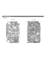
Страница 14: ...Model No XL 115 Ass y Name CD P C B P C B Pattern Layout 13...

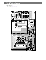
Страница 15: ...Model No XL 115 Ass y Name Front PCB 14 P C B Pattern Layout...

Страница 16: ...P C B Pattern Layout Model No XL 115 Ass y Name POWER PCB 15...

Страница 17: ...CE518 C ELECTRO CEXF1E470V 25V RSS 47MF 5X11 TP 99 JW544 545 WIRE JUMPER W581GY6095 AWG22 1 0 65 SN 6 AUTO 33 CE519 520 C ELECTRO CEXF1H479V 50V RSS 4 7MF 5X11 TP 100 JW546 WIRE JUMPER W581GY1005 AWG...

Страница 18: ...TO 168 R568 R CARBON FILM RD AZ101J 1 6 100 OHM J 61 JW334 345 WIRE JUMPER W581GY1005 AWG22 1 0 65 SN 10 AUTO 169 R569 R CARBON FILM RD AZ102J 1 6 1K OHM J 62 JW346 WIRE JUMPER W581GY7595 AWG22 1 0 65...

Страница 19: ...JUMPER W581GY1005 AWG22 1 0 65 SN 10 AUTO 192 R735 736 R CARBON FILM RD AZ103J 1 6 10K OHM J 126 JW790 792 WIRE JUMPER W581GY1005 AWG22 1 0 65 SN 10 AUTO 193 R737 R CARBON FILM RD AZ222J 1 6 2 2K OHM...

Страница 20: ...9 810 C ELECTRO CEXF1H109V 50V RSS 1MF 5X11 TP 22 CC263 C CERA CCXF1H103Z 50V F 0 01MF Z TAPPING 89 CE870 871 C ELECTRO CEXF1E470V 25V RSS 47MF 5X11 TP 23 CC264 C CERA CXCH1H820J 50V CH 82PF J TAPPING...

Страница 21: ...223 JW838 WIRE JUMPER W581GY6095 AWG22 1 0 65 SN 6 AUTO 157 JW108 WIRE JUMPER W581GY6095 AWG22 1 0 65 SN 6 AUTO 224 JW901 WIRE JUMPER W581GY1005 AWG22 1 0 65 SN 10 AUTO 158 JW109 WIRE JUMPER W581GY10...

Страница 22: ...J 1 6 1K OHM J 357 R652 653 R CARBON FILM RD AZ103J 1 6 10K OHM J 291 R241 R CARBON FILM RD AZ102J 1 6 1K OHM J 358 R654 655 R CARBON FILM RD AZ272J 1 6 2 7K OHM J 292 R243 244 R CARBON FILM RD AZ103J...

Страница 23: ...0 KKP419C KLCE 2F 0 75SQURE 6 CE980 C ELECTRO CEYF1E102V 25V RSS 1000MF 13X20 7 CW900 CONN WAFER 9728804100 22 10P P2 5 350 BOARD IN 8 D980 985 DIODE D1N4001 1N4001 9 F981 FUSE GLASS TUBE 5FSGB1222L S...

Отзывы: