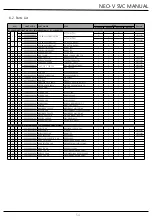
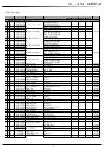
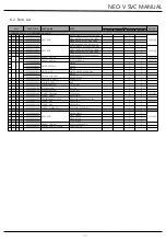
Daewoo NEO-V RCP33 Series Скачать руководство пользователя страница 54

NEO-V SVC MANUAL 

53 

8-2. Parts List 

NO 

PART-CODE 

PART NAME 

SPEC. 

Q'ty 

Remark 

RCP330 

RCP360 

RCT330 

RCT360 

A> CABINET 

A  0  1 

30100-0217300 

ASSY CAB URT 

RC-P330 


30100-0212400 

RC-P360 


A  0  2 

30117-0033800  SWITCH DR AS 

DOOR S/W AS HC-050K4 250V2.5A 


A  0  3 

30129-0021400  HINGE T R AS 

RCP346 


A  0  4 

30160-0001001  SPECIAL BOLT 

6*22 SWCH22A(WH) 


A  0  5 

30114-0093400  COVER HI T R 

RCP346 


A  0  6 

30109-0013400  CAP CAB COVER 

PP 


A  0  7 

90007-0003700  SCREW TAPPING 

T1 TRS 4*12 MFZN 


A  0  8 

30130-0000200  HODER POWER CODE 

PP(NATURAL) 


A  0  9 

40301-0101800  PCB MAIN ASSY 

NEO-V 


A  1  0 

30114-0091200  COVER CAB HRNS 

RCP346 


A  1  1 

30160-0001001  SCREW TAPPING 

6*22 SWCH22A(WH) 


A  1  2 

30114-0008102  COVER M PCB BOX AS 

EMBO PCM SCRAP(BACK COATING) 


A  1  3 

30160-0001001  SCREW TAPPING 

6*22 SWCH22A(WH) 


A  1  4 

40301-0081800  LAMP LED AS 

LAMP LED AS 5LED,DC12V 


A  1  5 

30155-0017300  WINDOW F LAMP 

GPPS 


A  1  6 

30125-0038500  GUIDE FRESH CASE *L 

PP 


A  1  7 

90007-0003700  SCREW TAPPING 

T1 TRS 4*12 MFZN 


A  1  8 

30125-0038600  GUIDE FRESH CASE *R 

PP 


A  1  9 

30109-0007600  CAP DV M HI HOLE 

ABS 


A  2  0 

30160-0006900  SPECIAL WASHER *M HI 

SGCC, T1.0XI.D9.0XO.D15 


A  2  1 

30129-0022000  HINGE M AS 

HINGE *M AS RCP346 


A  2  2 

30160-0001002  SPECIAL BOLT 

6X15 SWCH22A(WH) 


A  2  3 

30121-0001401  M FOOT ADJ AS 

PP(BLACK) 


A  2  4 

30123-0005701  GASKET CAB BASE 

GASKET CAB BASE PVC 

A++ 

A  2  5 

30129-0020900  HINGE *U AS 

HINGE *U AS NEO V-PJT 


A  2  5  a 

30129-0021000  HINGE_U 

PO, T5.0 


A  2  5  b 

30149-0006000  SHAFT U HI 

S20C, OD8 


A  2  5  c 

30121-0003800  FOOT ADJ AS 

PP+Insert RCP330,360 


A  2  6 

30160-0001001  SPECIAL BOLT *T 

T 6*22 SWCH22A(WH) 


B> MECH ROOM 


B  0  1 

30103-0034700  BASE COMP AS 

SBHG-A RCP330,360 


B  0  2 

30160-0001001  SPECIAL BOLT 

6*22 SWCH22A(WH) 


B  0  3 

60101-0000600  ABSORBER COMP 

ABSORBER COMP NBR 


B  0  4 

30160-0001300  SPECIAL WASHER COMP 

SK-5 T0.8XW22XL24.5 


B  0  5 

60110-0022200 

COMPRESSOR 

TH1114YL JIAXIPERA R600a 220 50 

A+ 

B  0  5  1 

60110-0022000 

LJ88DY1 DONPER R600a 220 60 

내수 1등급 

B  0  5  2 

60110-0021900 

LR88CY1 DONPER R600a 220 50 

A++ 

B  0  5  3 

60110-0022100 

LJ88XY1 DONPER R600a 127 60 

멕시코 

B  0  6 

60113-0006600  CORD POWER AS 

GPF REF, EU(LP-33) 


B  0  7 

60164-0002304 

CAPACITOR RUN SQ 

450V,4UF(WIRE HOUSING,CQC) 


B  0  7  1 

60164-0000800 

250V,12UF(WIRE HOUSING,CQC) 

멕시코 

B  0  8 

30112-0001501  CLAMP CORD 


B  0  9 

90007-0003700  SCREW TAPPING 

T1 TRS 4*12 


B  1  0 

60168-0002000  DRYER AS  

10 RCT(P)32/34/35* 


B  1  1 

30114-0098700  COVER MACH RM AS 

RCP330,360  


B  1  2 

30160-0003401  SCREW TAPPING 

TH1/W #8X1/2 MFZN 


B  1  3 

60144-0022600  PIPE SUC CONN RGP56 

DUCT1-0 OD6*T0.5 


B  1  4 

30153-0022100  SUPPORTER BASE CAB AS 

PP+FOAM-PU 

A++ 

B  1  5 

30132-0000100  HOSE DRN A2  

PVC 


B  1  7 

30111-0009100  CASE VAPORI AS 

CASE VAPORI AS PP(RECYCLE 100%) 

A+ 

B  1  7  a 

30111-0009001  CASE VAPORI 

PP 100% SCRAP 

A+ 

B  1  7  b 

60144-0027600  PIPE CONN A1 

C1220T-O OD4.76 * T0.5 * L286 

A+ 

B  1  7  c 

60118-0000801  FAN AS 

FAN AS FR-S690CG OD130 

A+ 

B  1  7  d 

60159-0010900  MOTOR C FAN 

타마스12 1.8W 1500rpm RGE51 

A+ 

B  1  8 


CASE VAPORI AS 


A++ 

B  1  8  a 


CASE VAPORI 


A++ 

B  1  8  b 


FAN OD110 


A++ 

B  1  8  c 


MOUTHBELL A1 35 


A++ 

B  1  8  d 


MOUTHBELL A2 35 


A++ 

B  1  8  e 

90007-0003700  SCREW TAPPING 

T1 TRS 4*12 MFZN 


A++ 

B  1  8 

60101-0002000  ABSORBER F MOTR 

ABSORBER F MOTR NBR 


A++ 

B  1  8  g 


OS MOTOR CFAN AC AS 


A++ 

B  1  8  h 

60101-0002000  ABSORBER F MOTR 

ABSORBER F MOTR NBR 


A++ 

B  1  8 


FIXTURE C MOTOR AC 36 


A++ 

B  1  8 

30160-0004701  SCREW T1 TRS 4_12 

SPECIAL SCREW T1 FLT 4X16 


A++ 

B  1  8  k 


PIPE WICON AS 


A++ 


Содержание NEO-V RCP33 Series

Страница 1: ...NEO V SVC MANUAL RCP33 36 RCT33 36...

Страница 2: ...ions for Safety 2 Product Specification 3 Wiring Diagram 4 Product Size and Features 5 Cooling Cycle 6 Product Control Information 7 Disassembly Assembly Guide of Each Part 8 Exploded View and SVC Par...

Страница 3: ...andard electrical components when replacing them 7 Make sure the hook is correctly engaged Remove dust and foreign materials from the housing and connecting parts 8 Do not fray damage machine heavily...

Страница 4: ...A Climate Class SN T Weight 69Kg 72Kg 74 5Kg 78Kg 2 2 Electrical Inlet Specification ITEM SPEC Model Name RCP3 RCT3 Cooling Components Comp Name TH1114Y1 A LR88CY1 A Oil MINERAL OIL 160ml TH1114Y1 200...

Страница 5: ...amp LED DC12V 0 6W Refrigerator Door Switch HC 050K4 AC 250 V 2 5A Power Code AC250V 16A F R Sensor REB303F31GA DW REB303F31GA 2 3 Refrigerator Control Temperature 4 REFRIGERATOR STEP DISPLAY ON OFF M...

Страница 6: ...NEO V SVC MANUAL 3 1 RCP3 Model Metal Door 3 Wiring Diagram 5...

Страница 7: ...NEO V SVC MANUAL 6 3 2 RCT3 Model Glass Door...

Страница 8: ...NEO V SVC MANUAL 3 3 Main PCB Circuit Diagram 7...

Страница 9: ...NEO V SVC MANUAL 8 3 3 Main PCB Circuit Diagram...

Страница 10: ...NEO V SVC MANUAL 9 3 3 Main PCB Circuit Diagram...

Страница 11: ...NEO V SVC MANUAL 10 3 3 Main PCB Circuit Diagram...

Страница 12: ...NEO V SVC MANUAL 11 3 3 Main PCB Circuit Diagram...

Страница 13: ...NEO V SVC MANUAL 12 3 3 Main PCB Circuit Diagram RCP3 Model...

Страница 14: ...NEO V SVC MANUAL 13 3 3 Main PCB Circuit Diagram RCT3 Model...

Страница 15: ...NEO V SVC MANUAL 14 4 1 Exterior Size RCP3 Model 4 Product Size and Features...

Страница 16: ...NEO V SVC MANUAL 4 1 Exterior Size RCT3 Model 15...

Страница 17: ...frigerator Compartment Freezer Compartment 1 Shelves 10 Freezer Case 2 LED Lamp 3 Multi Duct Air Flow 4 Vegetable Plus Option 5 Vegetable Case 6 Dairy Pocket Option 7 Utility Pocket 8 Water Tank Optio...

Страница 18: ...chine Room 1 Running Capacitor 11 Hot Pipe 2 Power Code 12 Pipe Absorber 3 Cover Relay 13 Suction Pipe 4 Special Washer 5 Dryer 6 Connect Pipe 7 Absorber Comp 8 Pipe WiCon 9 Case Vapori 10 Drain Hose...

Страница 19: ...chine Room A Model Machine Room 1 Running Capacitor 11 Bell Mouth 2 Power Code 12 Hot Pipe 3 Cover Relay 13 Pipe Absorber 4 Special Washer 14 Suction Pipe 5 Dryer 6 Absorber Comp 7 Connect Pipe 8 Pipe...

Страница 20: ...NEO V SVC MANUAL 5 Cooling Cycle 19...

Страница 21: ...rigerator Control 6 4 Special Mode Control 6 5 Comp Control 6 6 Defrost Control 6 7 Buzzer Control 6 8 Door Switch Control 6 9 Lamp Control 6 10 RS Heater Control 6 11 Function Switch Control Main PCB...

Страница 22: ...ff How to change Mode Push Func key Mode change sequence Mode Off Super Mode Eco Mode repeat 1 Temp Key it controls temperature of refrigerator by step Default 3step How to set temperature Push Temp k...

Страница 23: ...n it passes 1 minutes without key operation or door operation all led is off When there is operation for key or door at LED off condition led display is back to the normal state 2 Each MODE Display 1...

Страница 24: ...chanical 6 3 Refrigerator Control Input Output Front PCB Temp Key Refrigerator temperature A Dial Default Setting 3step B Refrigerator temperature setting at 25 Model Temperature Adjust 1step 2step 3s...

Страница 25: ...the fridge 2 Eco Mode For saving the power B Special Mode Operation 1 Super Mode Operation time 40 minutes COMP Continuously On On Off control 2 Eco Mode Operation time Unlimited COMP On Off control...

Страница 26: ...efrost Control 2 if Normal Mode R Sensor Error Compressor is controlled of the time by RT Sensor s range No R Sensor Error Compressor is controlled of the setting On Off point reference Refrigerator C...

Страница 27: ...ost CONTENTS EXPLANATION Inrush conditions If the temperature at the D sensor is under 3 5 C Defrost Mode starts When D Sensor Error is happened the initial defrost function isn t performed Each stage...

Страница 28: ...of COMP is 14hrs defrost mode starts immediately as long as total time COMP on time COMP off time is 72 hrs Each stage Release conditions PreCool R Sensor Comp Off Point 3 0 after 25 minutes Heater On...

Страница 29: ...diately If High Temp defrost mode is released normal defrost mode is performed C Low Temp Defrost Mode CONTENTS EXPLANATION Inrush conditions When RT Mode is Low A B Low Temp defrost mode starts immed...

Страница 30: ...on Comp is On Heater On 1 Inrush conditions after Precool completion 2 Operation Defrost Heater On Pause 1 Inrush conditions after Heater On completion 2 Operation Comp Defrost Heater Off Fan Delay 1...

Страница 31: ...er on After 2 seconds power s on the buzzer rings B Front Key Whenever PCB Control Panel button s pushed the buzzer rings C Test mode entry Operate mode changing sound As Forced Defrost Mode Demo Mode...

Страница 32: ...ch On Micom Low 0V signal Input 2 Door Close Door Close Door Switch Off Micom High 5V signal Input 6 9 Lamp Control A R Lamp 1 Door Switch Error R Lamp is always off 2 No Door Switch Error Door Open L...

Страница 33: ...eration Operation Test After power s on RS Heater On Off operation 5 times for 12 seconds 2 RS Heater Control Control Start From the time the comp off the initial one time controls R_S HTR Operation D...

Страница 34: ...Off Short Circuit On Short Circuit Off Short Circuit Off Power Saving Off Power Saving Off Power Saving On Power Saving Off As forced defrost Off As forced defrost Off As forced defrost Off As forced...

Страница 35: ...minutes Each stage Release conditions 1 Limited Time Limited Time Limited Time 2 D S 10 Parts Comp Off Off On Defrost HTR On Off Off F Fan Off Off Off 3 Mode release Auto closed after performing func...

Страница 36: ...ridge Temperature Bar 1 step LED On R Sensor Short Fridge Temperature Bar 1 step LED Twinkle RT Sensor Open Fridge Temperature Bar 2 step LED On RT Sensor Short Fridge Temperature Bar 2 step Twinkle D...

Страница 37: ...ue 1 step 2 step 3 step 4 step 5 step LED ON OFF 5 LED On 4 3 LED OFF 2 1 0 1 2 3 4 5 3 Mode release When it passes 5seconds without key operation auto closed the mode E Demo Mode 1 How to enter by pr...

Страница 38: ...int Max 3 0deg down 2 the following actions are recommended for service Resistance R52 Default resistance 31 4Kohms Resistance R53 Cut the J1 off to reduce basic resistance by 1 5 C 2K up Resistance R...

Страница 39: ...ens when D Sensor is sensing less than 45 D Sensor Short It happens when D Sensor is sensing more than 50 3 release When D Sensor is sensing from 45 to 50 D R Door Error 1 Error Code dr 2 Condition It...

Страница 40: ...e local environment and Micom Spec hardware function can be constrained B S W Constraint Depending on the amount of memory and CPU performance may be different from the S W performance results When op...

Страница 41: ...bly 7 1 Front FCP RCT3 Model 40 No Procedure No Procedure 1 4 Put Fixture FCP AS Fixture FCP FCP out Unscrew 2 points with driver 2 Remove top cover cap from top cap 3 5 After seperating FCP from Fixt...

Страница 42: ...AL 41 7 2 Front FCP RCP3 Model No Procedure No Procedure 1 3 Attach OPP tape on side of Front PCB Disconnect Front PCB lead wire to prevent scratch 2 Disassemble Front PCB with using flathead tools as...

Страница 43: ...re No Procedure 1 2 Insert a flathead tool Into a gap of door switch Disconnect the housing and change the switch to pull forward for a new one No Procedure No Procedure 1 3 Remove screw cap with driv...

Страница 44: ...Unscrew the fixing screw to remove the Louver F As Remove 3 screws in order to disassemble the Louver F As 2 5 Remove the Louver F As pulling the top side When disassembling check the Knob position 3...

Страница 45: ...EO V SVC MANUAL 44 7 6 LED Lamp Refrigerator No Procedure 1 Using a flathead tool Pull both locker and Separate a Window LED from Liner 2 Unscrew 2 points with driver 3 Disconnect LED PCB form housing...

Страница 46: ...the door cap 3 9 Disconnecting FCP housing Assemble top cover cap screw with driver 4 Remove top hinge 5 10 Remove door stopper located in under cap and Remove top cover cap screw with driver Reassemb...

Страница 47: ...der hinge and change it location to the opposite And also change the foot adjust location to the opposite Assemble top cover harness screw with driver 14 18 Assemble the under hinge shaft to the rever...

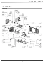
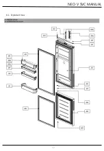
Страница 48: ...NEO V SVC MANUAL 8 1 Exploded View 8 Exploded View and SVC Parts List 47...

Страница 49: ...NEO V SVC MANUAL 48 8 1 Exploded View...

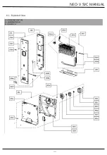
Страница 50: ...NEO V SVC MANUAL 49 8 1 Exploded View...

Страница 51: ...NEO V SVC MANUAL 50 8 1 Exploded View...

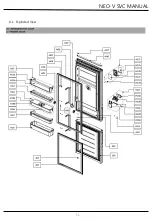
Страница 52: ...NEO V SVC MANUAL 51 8 1 Exploded View...

Страница 53: ...NEO V SVC MANUAL 52 8 1 Exploded View...

Страница 54: ...T 6 22 SWCH22A WH 1 1 1 1 B MECH ROOM B 0 1 30103 0034700 BASE COMP AS SBHG A RCP330 360 1 1 1 1 B 0 2 30160 0001001 SPECIAL BOLT 6 22 SWCH22A WH 4 4 4 4 B 0 3 60101 0000600 ABSORBER COMP ABSORBER COM...

Страница 55: ...D 0 2 30125 0009900 GUIDE DRN GA T0 4 1 1 1 1 E 0 1 30189 0015100 LOUVER F AS RCP330 360 E 0 1 a 30189 0014200 LOUVER F A1 PP RCP330 360 1 1 1 1 E 0 1 b 30134 0001900 KNOB F CONTL KNOB F CONTL PP 1 1...

Страница 56: ...T1 TRS 4 12 2 2 H 0 8 30126 0013800 HANDLE A TYPE ASSY RCP330 360 1 1 OPTION H 0 8 1 HANDLE B TYPE ASSY RCP330 360 1 1 OPTION H 1 9 30160 0005400 SPECIAL SCREW HNDL M5 L16 2 2 OPTION H 1 0 30109 00193...

Страница 57: ...0120 0012801 FIXTURE PCB WHITE SILVER BLACK ABS 1 1 J 3 3 b 40301 0102401 REF PCB SUB ASSY WHITE 1 1 40301 0102400 SILVER BLACK 1 1 J 0 3 c 60127 0023901 HARNESS R DR AS GLASS DOOR 1 1 J 0 4 30114 009...

Отзывы: