20
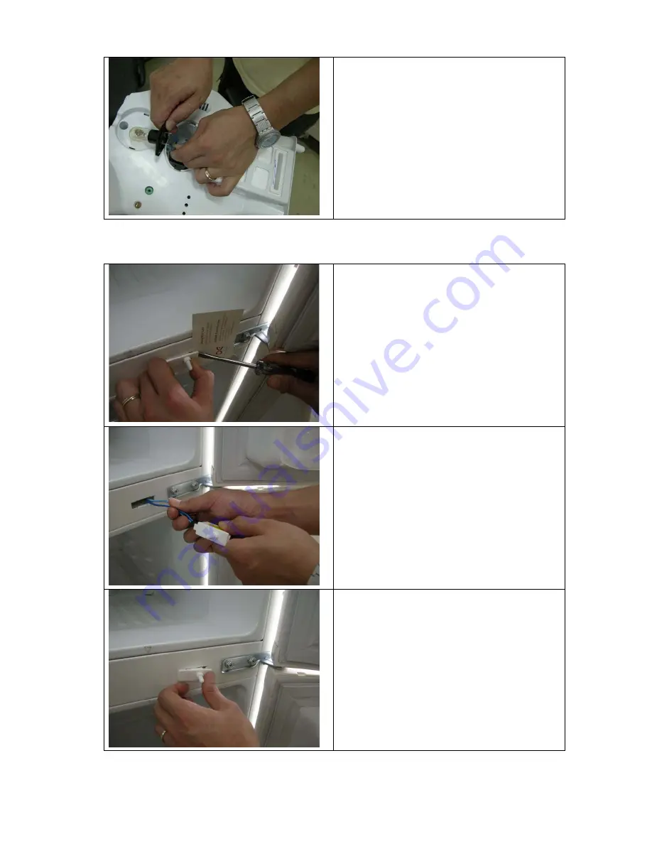
- Pull the lamp forward, then disassemble the
connector.
- The assembling procedure of new lamp is
the reverse of disassemble steps.
4. DOOR SWITCH PART
- In removing the door switch, push the door
switch left, insert a pointed rods as screw-
driver in the right gap, and push the rod left
and pull the door switch forward.
- Be careful not to harm the surface of cabinet
. (Use name plate etc. under the pointed rod)
- Pull the door switch forward and remove the
harness.
- In inserting new door switch, insert the left
part of the switch in the hole then push the
right part of refrigerator.
Содержание FR-291
Страница 1: ...1 SERVICE MANUAL Model FR 291 ...
Страница 3: ...3 2 NAME OF FARTS ...
Страница 4: ...4 3 AIR FLOW DIAGRAM ...
Страница 5: ...5 4 REFRIGERANT CYCLE DIAGRAM ...
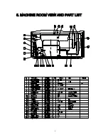
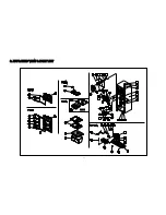
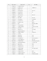
Страница 6: ...6 5 MACHINE ROOM VIEW AND PART LIST ...
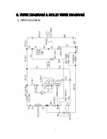
Страница 7: ...7 6 WIRE DIAGRAM SOLID WIRE DIAGRAM 1 WIRE DIAGRAM ...
Страница 8: ...8 2 SOLID WIRE DIAGRAM ...
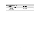
Страница 12: ...12 12 CONTL BOX HEATER FR 290 RATING AC 220V 4W RESISTANCE 12100 Ω ...
Страница 13: ...13 8 EXPLODED VIEW PART LIST ...

