

2
1) Before returning an instrument to the customer,
always make a safety check of the entire
instrument, including, but not limited to, the
following items:
(1) Be sure that no built-in protective devices are
defective or have been defeated during servicing.
(1) Protective shields are provided to protect
both the technician and the customer. Correctly
replace all missing protective shields, including
any remove for servicing convenience.
(2) When reinstalling the chassis and/or other
assembly in the cabinet, be sure to put back in
place all protective devices, including, but not
limited to, nonmetallic control knobs, insulating
fish papers, adjustment and compartment
covers/shields, and isolation resistor/capacitor
networks. Do not operate this instrument or
permit it to be operated without all protective
devices correctly installed and functioning.
(2) Be sure that there are no cabinet openings
through which adults or children might be able
to insert their fingers and contact a hazardous
voltage. Such openings include, but are not
limited to, excessively wide cabinet ventilation
slots, and an improperly fitted and/or incorrectly
secured cabinet back cover.
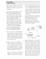
(3) Leakage Current Hot Check-With the
instrument completely reassembled, plug the
AC line cord directly into a 120V AC outlet. (Do
not use a isolation transformer during this test.)
Use a leakage current tester or a metering
system that complies with American National
Standards institute (ANSI) C101.1 Leakage
Current for Appliances and Underwriters
Laboratories (UL) 1270 (40.7). With the
instrument’s AC switch first in the ON position
and then in the OFF position, measure from a
known earth ground (metal water pipe, conduit,
etc.) to all exposed metal parts of the
instrument (antennas, handle brackets, metal
cabinets, screwheads, metallic overlays,
control shafts, etc.), especially and exposed
metal parts that offer an electrical return path
to the chassis.
Any current measured must not exceed 0.5mA.
Reverse the instrument power cord plug in the
outlet and repeat the test. See Fig. 1-1.
Any measurements not within the limits
specified herein indicate a potential shock
hazard that must be eliminated before returning
the instrument to the customer.
Fig. 1-1 AC Leakage Test
(4) Insulation Resistance Test Cold Check-(1)
Unplug the power supply cord and connect a
jumper wire between the two prongs of the plug.
(2) Turn on the power switch of the instrument.
(3) Measure the resistance with an ohmmeter
between the jumpered AC plug and all exposed
metallic cabinet parts on the instrument, such
as screwheads, antenna, control shafts, handle
brackets, etc. When an exposed metallic part
has a return path to the chassis, the reading
should be between 1 and 5.2 megohm. When
there is no return path to the chassis, the
reading must be infinite. If the reading is not
Device
Under
Test
Also test with Plug
reserved (Using AC
adapter Plug as
required)
2-Wire Cord
(Reading
should not
be above
0.5mA)
Test all
exposed Meter
Surfaces
Earth Ground
1. Precautions
1-1 Safety Precautions
Содержание DVC-T6300N
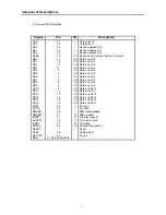
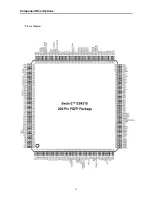
Страница 10: ...10 2 1 3 NTSC PAL Digital Video Encoder AD7170 Component Descriptions ...
Страница 11: ...11 Component Descriptions ...
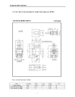
Страница 12: ...12 Component Descriptions ...
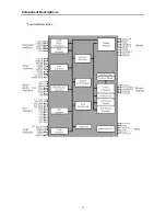
Страница 14: ...14 Functional Description Component Descriptions ...
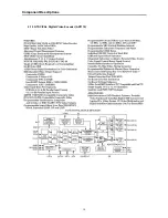
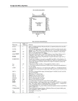
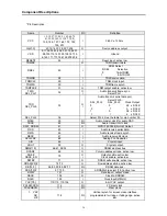
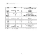
Страница 15: ...15 Component Descriptions Pinout Diagram ...
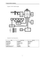
Страница 18: ...18 Block Diagram Component Descriptions 2 1 5 DIGITAL TO ANALOG STEREO AUDIO CONVERTER CS4391 ...
Страница 19: ...19 Component Descriptions ...
Страница 20: ...20 Component Descriptions ...
Страница 21: ...21 Component Descriptions ...
Страница 27: ...27 Component Descriptions 2 1 8 512K Bit CMOS 5 0 Volt only Uniform Sector Flash Memory A29040 ...
Страница 28: ...28 Component Descriptions ...
Страница 29: ...29 Component Descriptions 2 1 9 64MBit SDRAM 1MX 16BitX4Banks Synchronous DRAM LVTTL K4S641632D ...
Страница 30: ...30 Component Descriptions ...
Страница 31: ...31 Component Descriptions ...
Страница 54: ...54 9 PCB Diagrams 9 1 Main PCB Top ...
Страница 55: ...55 PCB Diagrams 9 2 Main PCB Bottom ...
Страница 56: ...56 9 3 Front PCB Top 9 4 Front PCB Bottom PCB Diagrams ...
Страница 57: ...57 9 5 SMPS PCB Top 9 6 SMPS PCB Bottom PCB Diagrams ...
Страница 58: ...58 10 Wiring Diagram ...
Страница 65: ...65 11 3 SMPS PCB Schematic Diagram 11 3 SMPS PCB Schematic diagram ...
Страница 66: ...66 1 27MHz 2 ROM DATA BUS 3 RAM DATA BUS 4 12C CLK 5 12C DATA 6 HSYNC 12 Oscillograms ...
Страница 67: ...67 7 VSYNC 8 BCLK DVD 9 LRCK DVD 10 TSDO 11 MCLK 12 HOST DATA Oscillograms ...
Страница 68: ...68 13 HOST CLK 14 HOST CS 15 MC DACO 16 MD DACO 17 VFD DATA 18 VFD STB Oscillograms ...
Страница 70: ...70 MEMO ...