Daewoo DV-K611 Скачать руководство пользователя страница 2

Worth Knowing

Please keep the video machine's guarantee card and receipt safe for warranty purposes.

Precautions

Read carefully through this manual to familiarize yourself with this
high–quality  Time Lapse video cassette recorder.

Make sure the rating of your household electricity supply matches that
shown on the back of the Time Lapse video cassette recorder.

Refer to this chapter and the "Initial installation" chapter to help you
install and adjust your Time Lapse video cassette recorder.
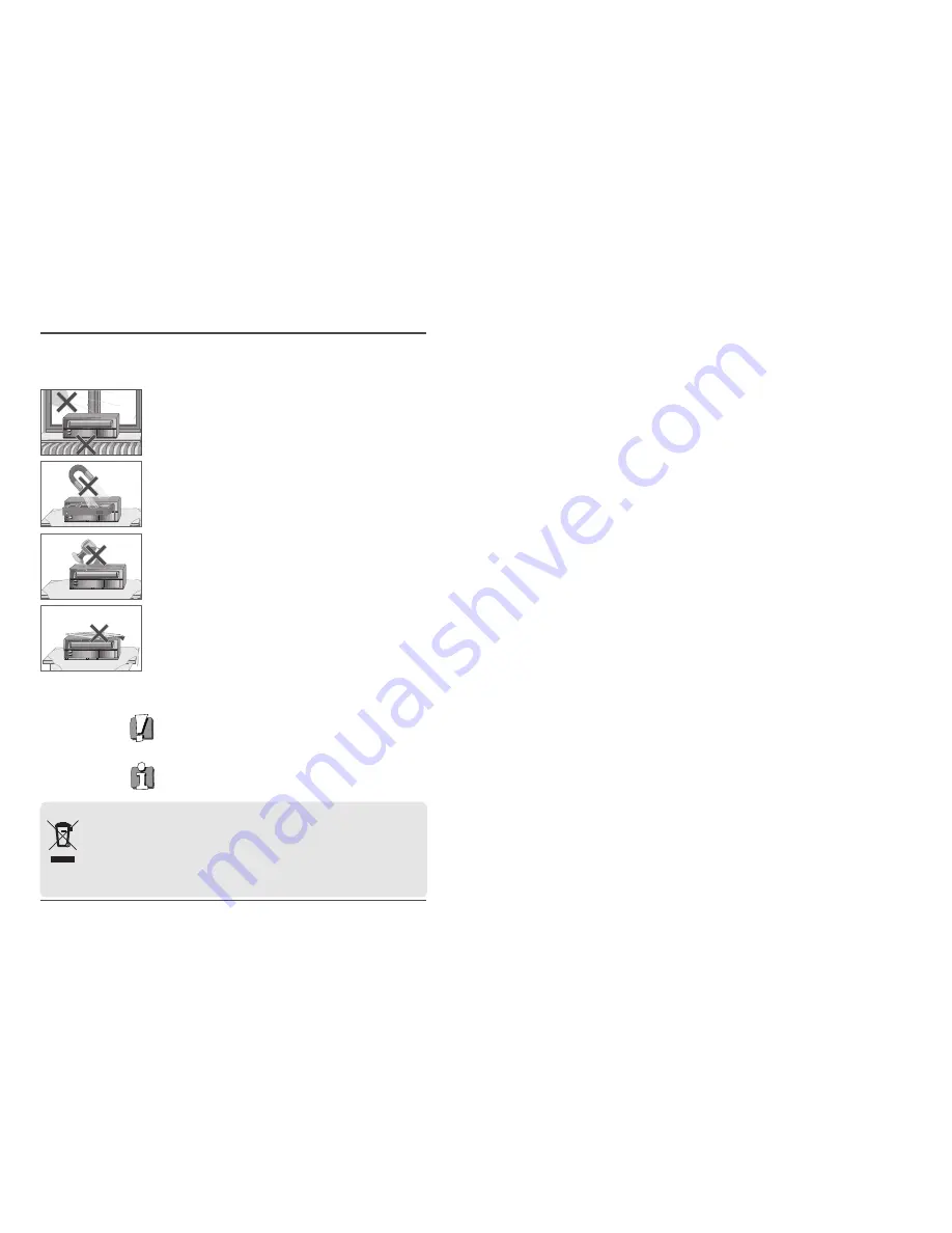
Do not ...
... expose the Time Lapse video cassette recorder to high levels of humidity

and heat, to avoid the risk of fire and electric shock.

... open the Time Lapse video cassette recorder. Have a qualified technician

carry out repairs.

... connect the Time Lapse video cassette recorder to the power supply if

you have just moved it from a cold to warm environment. This can result
in condensation inside the recorder and cause serious damage to the
machine and cassettes. Wait around two hours to allow it to reach room
temperature.

Make sure ...
... the recorder is placed on a steady, flat surface.
... you place the recorder where there is good ventilation all around.
... you clean the recorder only with a soft, lint–free cloth; do not use

aggressive or alcohol–based cleaning agents.

... you disconnect the power supply if the recorder appears to be working

incorrectly, is making an unusual sound, has a strange smell, has smoke
emitting from it or liquids have got inside it. Have a qualified technician
check the recorder.

... you disconnect the power supply and aerial if you will not be using the

recorder for a long period or during a thunderstorm.

For your own safety!

There are no components in this Time Lapse video cassette recorder
you can service or repair yourself. 

Do not open the case of the Time Lapse video cassette recorder. Only
allow qualified personnel to repair or service your set. 

This Time Lapse video cassette recorder is designed for continuous
operation. Switching it off does not disconnect it from the mains
(stand–by). To disconnect it from the mains, you have to unplug it. 

Recording any copyright protected material may infringe a copyright.

i.

Time Lapse Video Cassette Recorder

AUTO SET

CH.

OP   EJECT

Disposal of Used Electrical & Electronic Equipment

The meaning of the symbol on the product, its accessory or packaging indicates that this product shall not
be treated as household waste. Please, dispose of this equipment at your applicable collection point for the
recycling of electrical & electronic equipments waste. In the European Union and Other European countries
which there are separate collection systems for used electrical and electronic product. By ensuring the
correct disposal of this product, you will help prevent potentially hazardous to the environment and to
human health, which could otherwise be caused by unsuitable waste handling of this product. The recycling

of materials will help conserve natural resources. Please do not therefore dispose of your old electrical and electronic
equipment with your household waste. For more detailed information about recycling of this product, please contact
your local city office, your household waste disposal service or the shop where you purchased the product.

Содержание DV-K611

Страница 1: ...LAPSERECORDERWITH40HR REALTIMEREC User s Guide EV VCR960 EJECT REC Be sure to read carefully and follow all the SAFETY INFORMATION on page i Keep the manual in a safe place for future reference P N 97P95600D0 R8 ...

Страница 2: ... the power supply and aerial if you will not be using the recorder for a long period or during a thunderstorm For your own safety There are no components in this Time Lapse video cassette recorder you can service or repair yourself Do not open the case of the Time Lapse video cassette recorder Only allow qualified personnel to repair or service your set This Time Lapse video cassette recorder is d...

Страница 3: ...ote Control 5 Connections 6 Video Cassettes Tapes 7 Types of On screen displays and Display Sequence 8 Setting the Clock 10 Changing the On Screen Display 12 Normal Recording 14 Program Timer Recording 16 Alarm Recording 20 Panic Recording 23 Series Recording 23 Autorepeat Recording 25 Normal Playback 26 Normal Playback 26 Tracking Control 26 Audio Playback 26 Special Playback 27 Digital Shuttle 2...

Страница 4: ...eg 7 HOUR 07 MINUTE ERROR display eg E Error 04 Error No E 01 The cassette cannot be loaded or unloaded E 02 The tape stops E 03 The drum can not rotate properly E 04 The tape is cut broken E 05 The DEW Sensor Error AUDIO ON display eg A Audio 18H Play Speed 2 Time Lapse Video Cassette Recorder Digital Display 1 Operation Indicators display the actual operation mode 2 Cassette indicator Comes on w...

Страница 5: ...tton 21 REVERSE PLAY button 22 REC button 23 REC PLAY SPEED button 24 REC CHECK button 25 MENU button 4 Time Lapse Video Cassette Recorder Back Panel 1 ALARM 2 ALARM Input terminal 2 ALARM 3 ALARM Input terminal 3 WARNING OUT terminal 4 SERIES IN terminal 5 COM terminal 6 SERIES OUT terminal 7 SW OUT terminal 8 TAPE END terminal 9 PANIC IN terminal 10 COM terminal 11 ALARM OUT terminal 12 ALARM IN...

Страница 6: ...rformance Handling Cassette Tapes Cassette tapes should always be stored vertically in their cases away from high temperatures magnetic fields direct sunlight dirt dust and locations subject to mold formation Do not tamper with the cassette mechanism Never touch the tape with your fingers Protect cassette tapes from shocks or strong vibrations To Protect your recordings After having recorded a tap...

Страница 7: ...ted and the normal screen is displayed During recording or playback the menus cannot be displayed Press the MENU button First time Press the SHIFT button to move the arrow mark downward for the desired item Press the SHIFT button to select the desired item then the desired menu is displayed Press the MENU button to return to the normal screen from the initial menu Press the SHIFT button to select ...

Страница 8: ... last 2 digits only are displayed The day of the week is set automatically 12 Press the MENU button three times the normal screen is displayed The setting procedure is now complete Setting the Clock Example To set the clock to April 12 2010 at 9 30 Clock Setting 1 Turn the power on to all devices used 2 Press the MENU button the initial MENU is displayed The arrow mark is located in VCR Mode Set 3...

Страница 9: ... is changed identically 9 Press the SET or button to set the position of the counter and title to C Top or R Top or L Top If one of 2 items is set the position of 2 items is changed identically L Top C Top R Top Left Top Center Top Right Top L Bottom R Bottom Left Bottom Right Bottom 10 Press the MENU button three times the normal screen is displayed The setting procedure is now complete Changing ...

Страница 10: ...the display panel and recording starts 5 To stop recording press the STOP button If the Repeat Rec Set is set to NO in the REC MODE SET menu recording will continue to the end of the tape then stop and the tape will be ejected A tape recorded on this VCR cannot be played back on another make of time lapse VCR If you press on the REC button and the loaded cassette has no erasure prevention tab the ...

Страница 11: ...e display panel The VCR is now in timer recording stand by mode If the set stop time is earlier than or the same time as the set start time the VCR will consider the stop time to be the following day Program Timer Recording There are two program timer recording methods daily recording or recording on certain days of multiple weeks weekly recording Example 1 To record on every Thursday from 10 00 t...

Страница 12: ...ay panel The VCR internal battery is completely charged after the VCR has been connected to an AC power outlet for 48 hours and it will maintain all the VCR settings memory for up to 30 days Set the timer recordings so that the recording times do not overlap If they do the one with the earliest recording start time will have priority See chart below If the cassette tape is ejected while timer reco...

Страница 13: ...the SHIFT button to display the ALARM REC SET menu 5 Press the SHIFT button to select YES or NO YES The alarm recording takes place when there is alarm trigger input NO The alarm recording does not take place 6 Press the SHIFT button to set the Alarm speed 7 Press the SHIFT button to select the desired recording speed 3H 3 hour mode recording 6H 6 hour mode recording 18H 18 hour mode recording 30H...

Страница 14: ...the next only with VCRs of the same model as this one Series Recording Setup 1 Connect 2 VCRs or more as illustrated on next page 2 Set the following items as indicated Item VCR No 1 VCR No 2 and on Cassette tape Loaded Loaded Operation mode Stop Stop Repeat Rec Set NO NO Series Rec Set YES YES Timer recording OFF not set OFF not set Securitylockswitch SETLOCKswitch OFF ON Panic Recording This fea...

Страница 15: ...tton Recording will start When the tape s end is reached the VCR will rewind it to the beginning regardless of the counter memory and recording will resume If during autorepeat recording there is an alarm trigger is displayed on the display panel and alarm recording will take place Autorepeat recording will continue after alarm recording has completed its programmed duration 4 Set the security loc...

Страница 16: ...top playback press the STOP button To advanced or rewind the tape press the FF CUE or REW REVIEW button Tracking Control 1 While looking at the playback picture press and hold the TRACKING button to minimize the noise 2 If it cannot be minimized press the TRACKING button 3 If there is noise in the image during playback push the pause button Then while looking at the paused picture press and hold t...

Страница 17: ...igh speed 2 To return to normal playback press the PLAY button Still Image 1 Press the PAUSE STILL button during normal playback A still image can be viewed 2 To return to normal playback press the PLAY button With each press of the PAUSE STILL button the still image is advanced one image frame Vertical Lock Control During still image mode 1 Press the TRACKING button to reduce the vertical rolling...

Страница 18: ...base indication In 18 hour recording mode each second of the tape counter actually represents approximately 18 6 3 real seconds In the other LP recording speed modes 30H the tape counter indication is a ratio of the 6 hour mode base indication In 30 hour recording mode each second of the tape counter actually represents approximately 30 6 5 real seconds There may be a slight discrepancy between th...

Страница 19: ...he initial MENU 2 Press the SHIFT button to move the arrow mark to SW OUT Terminal Set 3 Press the SHIFT button to display the SW OUT TERMINAL SET menu 4 Press the SHIFT button to set FIELD or FRAME With each press of the SHIFT button the setting will change as indicated below 5 Press the SHIFT button to select Timing 6 Press the SHIFT button to set the TIMING AUTO When you connect with external e...

Страница 20: ...al MENU 2 Press the SHIFT button to move the arrow mark to Alarm Time 3 Press the SHIFT button to display the ALARM TIME menu The number of alarm triggers and the 35 most recent alarm recording times are displayed 4 Press the MENU button twice the normal screen is displayed Checking Power Loss Times 1 Press the MENU button to display the initial MENU 2 Press the SHIFT button to move the arrow mark...

Страница 21: ...his terminal is to connect to any external source such as a siren etc 1 High When an alarm input is received and the unit is recording the output becomes DC 5V Once the alarm recording is over the output returns to 0V 2 Low When an alarm input is received and the unit is recording the output becomes 0V Once the alarm recording is over the output returns to DC 5V PANIC INPUT Terminal 1 N C Normally...

Страница 22: ...der Connecting to a Multiview System for Alarm Recording ALARM 2 ALARM 3 If you are also using a Multi View system use the following diagrams as a guide to connecting the VCR for normal or alarm recording Connecting to a Multiview System for Normal Recording ALARM 2 ALARM 3 ...

Страница 23: ...the POWER STANDBY ON button Wait for the alarm recording to end Press the STOP button for 3 seconds to stop Wait for the panic recording to end Press the STOP button for 3 seconds to stop Cancel the security lock Load a cassette tape with erasure prevention tab or cover the tab hole with adhesive tape Be sure to select YES for autorepeat recording Set YES again for autorepeat recording Set the dat...

Страница 24: ...Alarm recording Noise in the playback picture The date and time are not recorded The cassette tape cannot be ejected The unit is not set to timer recording stand by mode N is selected for the TIMER PROGRAM SET NO is selected for alarm recording in the ALARM REC SET menu The tracking adjustment is in the wrong The video heads need cleaning NO is selected for the date and time in the DISPLAY SET men...

Страница 25: ...Ω unbalanced Audio Input RCA pin jack more than 47kΩ 8 8dBm unbalanced Output RCA pin jack less than 1 5kΩ 7 8dBm unbalanced Microphone input 60 dBs 3 5mm mini jack 10kΩ unbalanced Connectors Alarm input DC 4 5V Open DC 0 0 8V Closed 5 7kΩ Alarm output DC 4 5V H DC 0 0 8V L 1kΩ Panic input DC 4 5V Open DC 0 0 8V Closed 5 7kΩ End output DC 4 5V H DC 0 0 8V L 1kΩ Warning output DC 4 5V H DC 0 0 8V L...

Отзывы: