

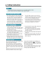


Safety Instruction
X-RAY RADIATION PRECAUTIONS
BEFORE SERVICING THIS CHASSIS READ THE “X-RAY RADIATION PRECAUTIONS”,
“SAFETY PRECAUTIONS” AND “PRODUCT SAFETY NOTICE” BELOW.
NOTE
1. Excessive high voltage can produce potentially hazard-
ous X-RAY RADIATION. To avoid such hazards, the
high voltage must not exceed the specified limit. The
nominal value of the high voltage of this receiver is
29kV(29”) at max beam current. The high voltage must
not, under any circumstances, exceed 30.5kV(29”).
Each time a receiver requires servicing, the high volt-
age should be checked. It is recommended the reading
of the high voltage recorded as a part of the service
recorded as a part of the service records. It is important
to use an accurate and reliable high voltage meter.
2. The only source of X-RAY RADIATION in this TV
receiver is the picture tube. For continuous RADIATION
protection, the replacement tube must be exactly the
same type tube as specified in the “PART LIST”.
SAFETY PRECAUTIONS
1. Potentials of high voltage are present when this
receiver is operating. Operation of the receiver outside
the cabinet or with the back cover removed involves a
shock hazard from the receiver.
1) Servicing should not be attempted by anyone who is
not thoroughly familiar with the precautions necessary
when working on high voltage equipment.
2) Always discharge the picture tube to avoid the shock
harzard before removing the anode cap.
3) Discharge the high potential of the picture tube before
handling the tube. The picture tube is highly evacuated
and if broken, glass fragments will be violently expelled.
2. If any FUSE in this TV receiver is blown, replace it will
the FUSE specified in the “PART LIST”.
3. When replacing a high wattage resistor (oxide metal
film resistor) in circuit board, keep the resistor 10mm
away from circuit board.
4. Keep wires away from high voltage or high temperature
components.
5. This receiver must operate between AC100~240 volts,
50/60Hz. NEVER connect to DC supply or any other
power or frequency.
PRODUCT SAFETY
Many electrical and mechanical parts in this chassis have
special safety-related characteristics.
These characteristics are often passed unnoticed by a
visual inspection and the X-RAY RADIATION protection
afforded by them cannot necessarily be obtained by using
replacement components rated for higher voltage, wattage,
etc.
Replacement parts which have these special safety char-
acteristics are identified in this manual and its supple-
ments, electrical components having such features are
identified by designated symbol on the “PART LIST”.
Before replacing any of these components, read the “PART
LIST” in this manual carefully.
The use of substitute replacement part which do not have
the same safety characteristics as specified in the “PART
LIST” may created X-RAY RADIATION.
Содержание DTY-29Z9
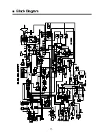
Страница 6: ...3 Block Diagram...
Страница 7: ...Block Diagram 3 1...
Страница 8: ......
Страница 9: ......
Страница 10: ......
Страница 11: ......
Страница 12: ......
Страница 13: ......
Страница 14: ......
Страница 15: ......
Страница 16: ......
Страница 17: ......
Страница 18: ......
Страница 19: ......
Страница 20: ......
Страница 21: ......
Страница 22: ......
Страница 23: ......
Страница 24: ......
Страница 25: ......
Страница 26: ......
Страница 27: ......
Страница 28: ......
Страница 29: ......
Страница 30: ......
Страница 31: ......
Страница 32: ......
Страница 33: ......
Страница 34: ......
Страница 35: ......
Страница 36: ......
Страница 37: ......
Страница 38: ......
Страница 39: ......
Страница 40: ......
Страница 41: ......
Страница 42: ......
Страница 43: ......
Страница 44: ......
Страница 45: ......
Страница 46: ......
Страница 47: ......
Страница 48: ......
Страница 49: ......
Страница 50: ......
Страница 51: ......
Страница 52: ......
Страница 53: ......
Страница 54: ......
Страница 55: ......
Страница 56: ......
Страница 57: ......
Страница 58: ......
Страница 59: ......
Страница 60: ......
Страница 61: ......
Страница 62: ......
Страница 63: ......
Страница 64: ......
Страница 65: ......
Страница 66: ......
Страница 67: ......
Страница 68: ......
Страница 69: ......
Страница 70: ......
Страница 71: ......
Страница 72: ......
Страница 73: ......
Страница 74: ......
Страница 75: ......
Страница 76: ......
Страница 77: ......
Страница 78: ......
Страница 79: ......
Страница 112: ...108 1 CM 915 u COM Circuit Schematics...
Страница 113: ...109 2 CM 915 MAIN...
Страница 114: ...110 3 CM 915 POWER DTC 29Z9...
Страница 115: ...34pow sch 1 Tue Oct 31 15 21 28 2000 110 1 3 1 CM 915 POWER DTC 34Z9...
Страница 116: ...111 4 CM 915 AV COMB...
Страница 117: ...112 5 CM 915 WOOFER SOUND TUNER...
Страница 118: ...113 6 CM 915 PIP...
Страница 119: ...114 7 CM 915 CRT...
Страница 120: ...115 8 CM 915 ETC...
Страница 121: ...116 Wave Form PAL Color Bar...
Страница 122: ...117 Exploded View DTC 29Z9...
Страница 123: ...118 Exploded View DTC 34Z9...