


-60-
IC DESCRIPTION
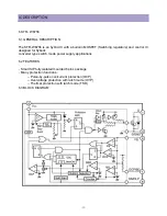
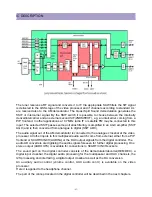
The base-band delay line is integrated. In devices without CVBS comb filter this delay line is
also active during NTSC to obtain a good suppression of cross colour effects. The demodulated
colour difference signals are internally supplied to the delay line. The baseband comb filter can
be switched off by means of the BPS bit (subaddress 3CH).
The subcarrier output is combined with a 3-level output switch (0 V, 2.1 V and 4.5 V). The
output level and the availability of the subcarrier signal is controlled by the CMB2-CMB0 bits.
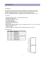
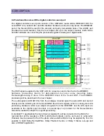
7.10 RGB output circuit
In the RGB control circuit the signal is controlled on contrast, brightness and saturation. The IC
has a YUV interface so that additional picture improvement ICs can be applied. To compensate
signal delays in the external YUV path the clamp pulse in the control circuit can be shifted by
means of the CLD bit in subaddress 44H. When the YUV interface is not required some of the
pins can be used for the insertion of RGB/YPrPb signals or as additional CVBS(Y)/C input.
When the YUV interface is not used one of the pins (VOUT) is transferred to general purpose
output switch (SWO1). The IC has also a YUV interface to th edigita ldie. Via this loop digital
features like “double window” are added.
A tint control is available for the base-band U/V signals. For this reason this tint control can be
activated for all colour standards. The signals for OSD and text are internally supplied to the
control circuit. The output signal has an amplitude of about 1.2V black-to-white at nominal input
signals and nominal settings of the various controls.
A black level off-set can be made with respect to the level which is generated by the black current stabilization
system. In this way different colour temperatures can be obtained for the bright and the dark part of the
picture. The black level control is active on the Red and the Green output signal. It is also possible to control
the black level of the Blue and the Green output signal (OFB bit = 1).
In the Vg2 adjustment mode (AVG=1) the black current stabilization system checks the output
level of the 3 channels and indicates whether the black level of the highest output is in a certain
window(WBC-bit) or below or above this window (HBC-bit). This indication can be read from the
status byte 01 and can be used for automatic adjustment of the Vg2 voltage during the
production of the TV receiver. During this test the vertical scan remains active so that the
indication of the 2 bits can be made visible on the TV screen.
The control circuit contains a beam current limiting circuit and a peak white limiting circuit. The
control is realised by means of a reduction of the contrast and brightness control settings. The way
of control (first contrast and then brightness or contrast and brightness in parallel) can be chosen by
means of the CBS bit (subaddress 44H). The peak white level is adjustable via the I2C-bus.
To prevent that the peak white limiting circuit reacts on the high frequency content of the video signal a
low-passfilter is inserted in front of the peak detector. The circuit also contains a soft-clipper which
prevents that the high frequency peaks in the output signal become too high. The difference between the
peak white limiting level and the soft clipping level is adjustable via the I2C-bus in a few steps.
During switch-off of the TV receiver a fixed beam current is generated by the black current
control circuit. This current ensures that the picture tube capacitance is discharged. During the
switch-off period the vertical deflection can be placed in an overscan position so that the
discharge is not visible on the screen.
A wide blanking pulse can be activated in the RGB outputs by means of the HBL bit in subaddress 43H.
The timing of this blanking can be adjusted by means of the bits WBF/R bits in subaddress 26H.
Содержание DTU-29M5ME
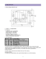
Страница 5: ...4 3 CIRCUIT BLOCK DIAGRAM...
Страница 16: ...15 5 CM 500 F TYPICAL SERVICE DATA...
Страница 26: ...25...
Страница 27: ...26...
Страница 28: ...27...
Страница 29: ...28...
Страница 30: ...29 DTU 29M5...
Страница 31: ...30 DTU 29M6...
Страница 32: ...31 DTU 29M7...
Страница 33: ...32 DTU 29U1...
Страница 35: ...34 CM 500F 4858311110 DTU 29U8 4859645360 12W 8 SP 58126F DTU 29U8...
Страница 36: ...35 DTU 29F1 CM 500F 4859845360 CPT A68AKY13X CM 500F CM 500F DTU 29F1...
Страница 37: ...36 DTU 29F2 CM 500F 4859845360 CPT A68AKY13X CM 500F DTU 29F2...
Страница 38: ...37 DTU 29F3 CM 500F 4859845360 CPT A68AKY13X CM 500F CM 500F DTU 29F3...
Страница 40: ...39 IC DESCRIPTION...
Страница 77: ...DAEWOO ELECTRONICS CORP PRINTED DATE 686 AHYEON DONG MAPO GU SEOUL KOREA C P O BOX 8003 SEOUL KOREA JULY 2005...