background image

-7-

ALIGNMENT INSTRUCTION

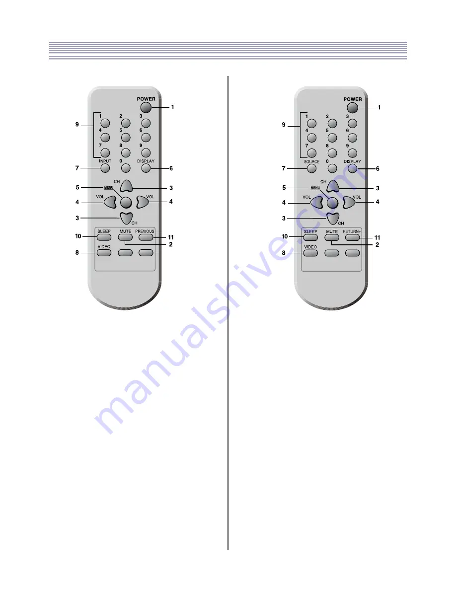
1.POWER

Use this button to turn your TV on or off.

2.MUTE

Use to turn the TV’s sound on and off.

3.

W

CH

V

Use these buttons to change channels on your TV, or select items
in the menu system.

4.

C

VOL

B

Use these buttons to change your TV's volume, to activate selec-
tions in the menu system, or to change audio and video settings.

5.MENU

Use this button to turn the TV’s menu system on and off.

6.DISPLAY

Use this button to display the present status.

7.SOURCE

Use this button to select the TV’s signal source.

8.VIDEO

Use this button to display video adjustment 
items.

9.0-9

Use these buttons to change channels.

10. SLEEP

Use this button to program the TV to turn off after a certain time.

11.

Use this button to return to the previous channel you were
watching.

1.POWER

Use this button to turn your TV on or off.

2.MUTE

Use to turn the TV’s sound on and off.

3.

W

CH

V

Use these buttons to change channels on your TV, or select items
in the menu system.

4.

C

VOL

B

Use these buttons to change your TV's volume, to activate selec-
tions in the menu system, or to change audio and video settings.

5.MENU

Use this button to turn the TV’s menu system on and off.

6.DISPLAY

Use this button to display the present status.

7.INPUT

Use this button to select the TV’s signal source.

8.VIDEO

Use this button to display video adjustment 
items.

9.0-9

Use these buttons to change channels.

10. SLEEP

Use this button to program the TV to turn off after a certain time.

11. PREVIOUS

Use this button to return to the previous channel you were
watching.

Your Remote Control(R-48C04)

R-48C12

Содержание DTH-2930SSFV

Страница 1: ...ing their performance without notice in the parts list So if you need the latest parts information please refer to PPL Parts Price List in Service Information Center Service Manual Color Television S...

Страница 2: ...TDA6107AJF 24 24WC16 16 KB EEPROM 25 LA42072N E AUDIO AMPLIFIER 26 STR W6735 56 27 WAVEFORMS 28 TROUBLE SHOOTING GUIDE 30 NO POWER 30 NO PICTURE 31 NO SOUND 32 CH DON T MEMORY or SKIP 33 NO COLOR 34 N...

Страница 3: ...COLOR SETS ALWAYS RE INSTALL THEM 3 IT IS ESSENTIAL THAT SERVICE PERSONNEL HAVE AVAILABLE AN ACCU RATE AND RELIABLE HIGH VOLTAGE METER THE CALIBRATION OF THE METER SHOULD BE CHECKED PERIODICALLY AGAIN...

Страница 4: ...ust be corrected imme diately The lightning flash with arrowhead symbol within an equilateral triangle is intended to alert the service personnel to the presence of uninsu lated dangerous voltage that...

Страница 5: ...entilation 4 Wall and shelf mounted installations using a commercial mounting kit must follow the factory approved mounting instructions A receiver mounted to a shelf or platform must retain its origi...

Страница 6: ...84 Sound Output 6W 6W Speaker 8 ohm 12W x 2EA Antenna Input Impedance 75 ohm Unbalanced Auxiliary Input Terminal Side Video Audio L R AV2 Rear Video Audio L R AV1 S Video Y Cb Cr Audio L R CVI Auxilia...

Страница 7: ...6 CIRCUIT BLOCK DIAGRAM AC 120 220V 50 60Hz 250V 65V 139 5V D801 195V 139 5V...

Страница 8: ...a certain time 11 RETURN Use this button to return to the previous channel you were watching 1 POWER Use this button to turn your TV on or off 2 MUTE Use to turn the TV s sound on and off 3 WCHV Use...

Страница 9: ...hannel up or channel down button select the item you wish to adjust The color of selected item turns into the blue Press the volume up or down button to enter in the service mode you wish to adjust 2...

Страница 10: ...9 ALIGNMENT INSTRUCTION...

Страница 11: ...the AGC item in service mode it s two way to entering the AGC item in service mode Enter the service mode and select service adjustment S5 and select AUTO AGC Enter the service mode and select service...

Страница 12: ...R data value to center the raster properly on the screen 4 3 Vertical Size Adjustment Select V SIZE item adjust V SIZE data value to proper vertical size as follows 4 4 Horizontal Position Adjustment...

Страница 13: ...STRUCTION 4 4 EAST WEST Adjustment Adjust the H PARALLEL H SIZE H BOW PARABOLA EW TRAPEZ CORNER TOP CORNER BOTTOM to compensate for geometrical distortion H PARALLEL H SIZE PARABOLA CORNER TOP CORNER...

Страница 14: ...13 ALIGNMENT INSTRUCTION...

Страница 15: ...14 IC DESCRIPTION 1 1 UOC III BLOCK DIAGRAM 1 UOC III SERIES...

Страница 16: ...1 7 SDA P1 6 SCL1 VDDP 3 3 XTALOUT XTALIN P3 3 ADC3 P3 1 ADC1 VDDA1 3 3V VSSA1 P3 2 ADC2 VDRA VIFIN1 VIFIN2 VSC SECPLL DECDIG PH1LF DECBG AVL EWD VDRB IREF AGCOUT DVBIN1 SIFIN1 DVBIN2 SIFIN2 VP1 GNDIF...

Страница 17: ...C 0 V VREF_POS_HPR 16 positive reference voltage SDAC 3 3 V XTALIN 18 crystal oscillator input XTALOUT 19 crystal oscillator output VSSA1 20 ground VGUARD SWIO 69 V guard input I O switch e g 4 mA cur...

Страница 18: ...put AUDIOIN5L 36 audio 5 input left signal AUDIOIN5R audio 5 input right signal AUDOUTSL 37 audio output for SCART CINCH left signal AUDOUTSR 38 audio output for SCART CINCH right signal DECSDEM 72 de...

Страница 19: ...ht signal CVBS2 Y2 52 CVBS2 Y2 input AUDIOIN3 audio 3 input AUDIOIN3L 53 audio 3 input left signal AUDIOIN3R 54 audio 3 input right signal CVBS3 Y3 55 CVBS3 Y3 input C2 C3 56 chroma 2 3 input AUDOUTLS...

Страница 20: ...input Y input or CVBS YX input YSYNC 73 Y input for sync separator YOUT 74 Y output for YUV interface UOUT INSSW2 U output for YUV interface 2nd RGB YPBPR insertion input VOUT SWO1 V output for YUV i...

Страница 21: ...xternal interrupt 0 or port 0 5 4 mA current sinking capability for direct drive of LEDs P1 0 INT1 4 port 1 0 or external interrupt 1 P1 1 T0 5 port 1 1 or Counter Timer 0 input VDDC2 3 digital supply...

Страница 22: ...0 input P3 1 ADC1 13 port 3 1 or ADC1 input VDDC1 3 digital supply to core 1 8 V DECV1V8 3 decoupling 1 8 V supply P3 2 ADC2 14 port 3 2 or ADC2 input P3 3 ADC3 15 port 3 3 or ADC3 input VSSC P 1 digi...

Страница 23: ...22 IC DESCRIPTION 2...

Страница 24: ...23 IC DESCRIPTION...

Страница 25: ...24 IC DESCRIPTION 3...

Страница 26: ...25 IC DESCRIPTION 4...

Страница 27: ...26 IC DESCRIPTION...

Страница 28: ...INPUT OF POWER SUPPLY FOR CONTROL CIRCUIT 5 SS OLP DELAY AT OVERLOAD SOFT START SET UP TERMINAL OVERLOAD PROTECTION AND SOFT START OPERATION TIME SET UP 6 FB FEEDBACK TERMINAL CONSTANT VOLTAGE CONTRO...

Страница 29: ...28 WAVEFORMS Appendix WAVEFORMS 1 I801 PIN1 2 T402 FBT HOR OUT 3 T402 FBT 190V D406 4 I701 PIN73 HOUT 5 I701 PIN76 V OUT 6 I701 PIN76 V OUT...

Страница 30: ...29 WAVEFORMS Appendix 7 I701 PIN75 EW OUT 8 I701 PIN46 MONITOR OUT 9 I701 X TAL 10 I301 PIN4 V OUT 11 I901 PIN R IN 12 I901 PIN R OUT...

Страница 31: ...30 1 NO POWER TROUBLESHOOTING GUIDE Appendix...

Страница 32: ...1 SAW FILTER IF SCL SD 33V 5V CHECK THE VOLTAGE 7 8 I701 CHECK CLOCK DATA 18 19 X701 24 576MHz CHECK THE CRYSTAL 5V 3 3V 22 43 45 63 80 9 16 86 88 CHECK THE VOLTAGE I701 73 CHECK THE HOUT 83 84 85 CHE...

Страница 33: ...THE VOLTAGE 7 8 I701 CHECK CLOCK DATA 18 1 X701 24 576MHz CHECK THE CRYSTAL 5V 3 3V 22 43 45 63 80 9 16 86 88 I601 LA42072N 7 13V Z101 SAW FILTER SIF CHECK THE VOLTAGE 33 CHECK THE VOLTAGE AUDIO INPUT...

Страница 34: ...To The Figure E NG Loss of Signal or Weak Signal TU101 TUNER Z101 SAW FILTER IF SCL SD 33V 5V CHECK THE VOLTAGE 7 8 I701 CHECK CLOCK DATA 18 19 X701 24 576MHz CHECK THE CRYSTAL 5V 3 3V Z101 SAW FILTE...

Страница 35: ...43 45 63 80 9 16 86 88 CHECK THE VOLTAGE I701 CHECK THE RGB OUT I301 TDA8358J CHECK THE VERTICAL SIGNAL 83 84 85 CHECK THE CRYSTAL X701 24 576MHz CHECK THE CRYSTAL 18 19 VERTICAL 76 77 1 2 4 VERTICAL...

Страница 36: ...35 TROUBLESHOOTING GUIDE Appendix...

Страница 37: ...R AS DTQ 29U1V 22 PA601 4850704S32 CONNECTOR YH025 04 YRT205 ULW 900 23 SP601 4858310810 SPEAKER SP 58126F01 24 SP602 4858310810 SPEAKER SP 58126F01 25 JA02 4859105450 JACK PIN BOARD YSC03P 4120 9S 26...

Страница 38: ...HEAT SINK ASS Y 1LA42072N 7174300811 63 00001 1LA42072N IC AUDIO AMP LA42072N 64 0000A 4857028200 HEAT SINK AL EX BK 65 0000B 7174300811 SCREW TAPPTITE TT2 RND 3X8 MFZN 66 I701 1DA12001PQ IC MICOM FLA...

Страница 39: ...STOR SVC471D14A BULK 109 C404 CEXA2D229E C ELECTRO 200V RUL 2 2MF 10X16 TP 110 C410 CMXB2G472J C MYLAR 400V EU 4700PF J TP 111 C411 CEXF2E100V C ELECTRO 250V RSS 10MF 10X20 TP 112 C412 CCXB3D681K C CE...

Страница 40: ...50V RSS 2 2MF 5X11 TP 152 C112 CMXM2A682J C MYLAR 100V 6800PF J TP 153 C114 CEXF1H109V C ELECTRO 50V RSS 1MF 5X11 TP 154 C115 CMXL1J224J C MYLAR 63V MEU 0 22MF J TP 155 C116 CCXF1H223Z C CERA 50V F 0...

Страница 41: ...H478V C ELECTRO 50V RSS 0 47MF 5X11 TP 198 C623 CEXF1H478V C ELECTRO 50V RSS 0 47MF 5X11 TP 199 C624 CMXL1J104J C MYLAR 63V MEU 0 1MF J 200 C625 CMXL1J104J C MYLAR 63V MEU 0 1MF J 201 C626 CMXL1J104J...

Страница 42: ...102K C CERA 50V B 1000PF K TAPPING 240 CA08 CCXB1H102K C CERA 50V B 1000PF K TAPPING 241 CV12 CEXF1C470V C ELECTRO 16V RSS 47MF 5X11 TP 242 F801 5FWPS5022L FUSE WIDE TL 250V 5A CASE 243 I804 1K1A431B...

Страница 43: ...286 C720 CBZF1H104Z C CERA SEMI 50V F 0 1MF Z 287 C728 CCZF1H103Z C CERA 50V F 0 01MF Z 288 C733 CBZF1H104Z C CERA SEMI 50V F 0 1MF Z 289 C736 CCZB1H102K C CERA 50V B 1000PF K AXIAL 290 C738 CCZB1H10...

Страница 44: ...333 L703 5CPZ479K02 COIL PEAKING 4 7UH K AXIAL 3 5MM 334 L704 5CPZ479K02 COIL PEAKING 4 7UH K AXIAL 3 5MM 335 L705 5CPZ479K02 COIL PEAKING 4 7UH K AXIAL 3 5MM 336 L706 5CPZ479K02 COIL PEAKING 4 7UH K...

Страница 45: ...02F R METAL FILM 1 6 12K OHM F 377 R413 RD 4Z470J R CARBON FILM 1 4 47 OHM J 378 R418 RD 4Z102J R CARBON FILM 1 4 1K OHM J 379 R601 RD AZ622J R CARBON FILM 1 6 6 2K OHM J 380 R602 RD AZ102J R CARBON F...

Страница 46: ...R723 RD AZ122J R CARBON FILM 1 6 1 2K OHM J 423 R725 RD AZ513J R CARBON FILM 1 6 51K OHM J 424 R726 RD AZ101J R CARBON FILM 1 6 100 OHM J 425 R727 RD AZ102J R CARBON FILM 1 6 1K OHM J 426 R729 RD AZ10...

Страница 47: ...FILM 1 6 10K OHM J 467 R835 RD AZ103J R CARBON FILM 1 6 10K OHM J 468 R873 RD AZ391J R CARBON FILM 1 6 390 OHM J 469 RA03 RD AZ224J R CARBON FILM 1 6 220K OHM J 470 RA04 RD AZ224J R CARBON FILM 1 6 2...

Страница 48: ...SIBLE 1W 1 OHM J TAPPING 511 C902 CCXB1H561K C CERA 50V B 560PF K TAPPING 512 C903 CMXL2E104K C MYLAR 250V MEU 0 1MF K 513 C922 4SG0DX0001 SPARK GAP SSG 102 A1 1 0KV TAP 514 C923 4SG0DX0001 SPARK GAP...

Страница 49: ...48...

Страница 50: ...49...

Страница 51: ...50...

Страница 52: ...51...

Страница 53: ...52...

Страница 54: ...DAEWOO ELECTRONICS CORP PRINTED DATE MAY 2006 686 AHYEON DONG MAPO GU SEOUL KOREA C P O BOX 8003 SEOUL KOREA...

Отзывы: