- 6 -
APPENDIX
PIN NAME
FUNCTION
INTERFACE
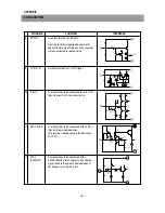
13
CW OUT
An output terminal for the continuous chroma
sub-carrier frequency wave, with an amplitude
of 0.7Vp-p (typ).
Also the dc level shows chroma killer status,
with a level of 3.5V for B/W and 1.5V for
Color.
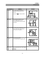
14
RGB VCC(9V)
A Vcc terminal for RGB block, PIF det. Output
and sound output circuit.
-
Supply 9V.
15
YS/YM SW
A terminal for switching of EXT RGB Mode
/Spot killer
and fast Half tone.
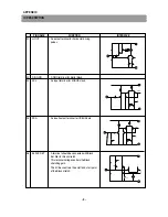
16
EXT.R IN
Input terminals for EXT RGB signals. The
17
EXT.G IN
signals are clamped by capacitors, therefore
18
EXT.B IN
the input impedance should be low, 100 ohms
or less is recommended.
For this input, the brightness and RGB
contrast is adjustable, the ABL/ACL limits the
output level. This ABL/ACL may be turned On
and OFF.
OFF : for small area like OSD
ON : for large area like TELETEXT
(input level 0.7Vp-p/100IRE)
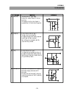
19
Y/C GND
The GND terminal for Y/C circuit.
20
R OUT
Terminals for R/G/B signal output.
21
G OUT
Connect resistances to GND, for the current
22
B OUT
source if the slew rate is not enough. Due to
the source current limitation, the resistances
should be 2.0 or more.
-
IC DESCRIPTION
Содержание DTD-29U8ME
Страница 5: ...4 CIRCUIT BLOCK DIAGRAM...
Страница 12: ...SCHEMATIC DIAGRAM 11...
Страница 13: ...PRINTED CIRCUIT BOARD PCB MAIN 12...
Страница 14: ...13 PRINTED CIRCUIT BOARD...
Страница 15: ...14 PRINTED CIRCUIT BOARD...
Страница 16: ...15 SCHEMATIC DIAGRAM DAEWOO ELEC CO LTD CM 905 CM 905F PIP BOARD 2000 11 13 REVISION PIP 1 S N 4859811724...
Страница 17: ...16 PRINTED CIRCUIT BOARD...
Страница 18: ...17 PRINTED CIRCUIT BOARD...
Страница 19: ......


