background image

ESPAÑOL

45

Requisitos de instalación

Requisitos eléctricos

IMPORTANTE

Respete todos los códigos y ordenanzas vigentes.

Es responsabilidad del cliente:

• 

Para contactar con un instalador eléctrico cualificado.

•  Para asegurarse de que la instalación eléctrica es 

adecuada y cumple con el Código Eléctrico Nacional, 

ANSI/NFPA 70 - última edición*, o las normas CSA 

C22.1-94, Código Eléctrico Canadiense, Parte 1 y C22.2 

No.0-M91 - última edición** y todos los códigos y 

ordenanzas locales.

Si los códigos lo permiten y se utiliza un cable de tierra 

separado, se recomienda que un electricista cualificado 

determine que la trayectoria de la tierra es adecuada.

Se puede obtener una copia de las normas de los códigos 

anteriores en:

National Fire Protection Association

1 Batterymarch Park

Quincy, MA 02169-7471

CSA International

8501 East Pleasant Valley Road

Cleveland, OH 44131-5575
•  Se requiere un circuito eléctrico de 120 voltios, 60 Hz., 

sólo CA, 15 amperios, con fusible.

•  Si la casa tiene cableado de aluminio, siga el 

procedimiento siguiente.

1.  Conecte una sección de cable de cobre sólido a los 

cables flexibles.

2.  Conecte el cableado de aluminio a la sección 

añadida de cable de cobre utilizando conectores y/o 

herramientas especiales diseñadas y homologadas 

por UL para unir cobre con aluminio.

•  Siga el procedimiento recomendado por el fabricante 

del conector eléctrico. La conexión de aluminio/cobre 

debe cumplir con los códigos locales y las prácticas de 

cableado aceptadas por la industria.

• 

Los tamaños de los cables y las conexiones deben 

ajustarse a la capacidad del aparato, tal como se 

especifica en la placa de características del modelo/

serie. La placa de modelo/serie se encuentra detrás 

del filtro en la pared posterior de la campana 

extractora.

• 

Los tamaños de los cables deben cumplir con los 

requisitos del Código Eléctrico Nacional, ANSI/NFPA 

70 (última edición), o las normas CSA C22. 1-94, 

Código Eléctrico Canadiense, Parte 1 y C22.2 Nº 0-M91 

(última edición y todos los códigos y ordenanzas 

locales).

Содержание DHD U990C/DA Series

Страница 1: ...LIB0179901 Installation Instructions Instructions d Installation Instrucciones para instalaci n Pro CanopyWall Hood Hotte murale Pro Canopy Campana de pared Pro Canopy DHD U990C DA...

Страница 2: ...irements 8 Venting methods 8 Ducting options 9 What is in the box 10 Tools and parts 10 Dimentions and clearances 11 Accessories Sold Separately 11 Installation 12 Installation instructions 12 Outside...

Страница 3: ...this manual forpersonal and professional reference CustomerService To resolve questions and installation issues contact yourDacordealerorDacorcustomerservice Before calling have the hood s model and s...

Страница 4: ...it in a safe place forfuture reference State of California Proposition 65 warning US only WARNING This product contains chemicals known to the State of California to cause cancerand birth defects oro...

Страница 5: ...Forproducts sold in the US and Canadian markets only channels1 11 are available You cannot select any otherchannels IC RADIATION EXPOSURE STATEMENT This equipment complies with IC RSS 102 radiation ex...

Страница 6: ...IRE OBSERVE THE FOLLOWING PRECAUTIONS SMOTHER FLAMES with a close fitting lid cookie sheet ormetal tray then turn off the burner BE CAREFUL TO PREVENT BURNS If the flames do not go out immediately EVA...

Страница 7: ...ey Road Cleveland OH 44131 5575 A120 volt 60 Hz AC only 15 amp fused electrical circuit is required If the house has aluminum wiring follow the procedure below 1 Connect a section of solid copperwire...

Страница 8: ...its the house Hood must be vented to the outside of building only Discharge direction This hood is factory set forventing through the roof vertical discharge orwall horizontal discharge To vent throug...

Страница 9: ...ore making cutouts make sure there is proper clearance within the ceiling orwall forthe exhaust vent Mounting height CAUTION Mount this hood so that the bottom edge above the cooking surface is at 30...

Страница 10: ...48 Double fan Tools and parts Removing the packaging CAUTION Remove the carton carefully Weargloves to protect against sharp edges WARNING Remove the protective film before putting into operation Par...

Страница 11: ...in relief 3 UL listed wire connectors 1 wall orroof cap Metal vent system Dimentions and clearances A B E G H I F D C 30 36 48 A 30 76 cm 36 91 2 cm 48 121 7 cm B 25 63 2 cm C 18 45 7 cm D 12 30 5 cm...

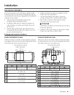
Страница 12: ...ust NOTE This hood is factory set to vent through the top airexit 3 Select a flat surface forassembling the hood Place a covering overthat surface Outside top exhaust Top installation diagram Use the...

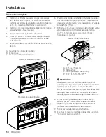
Страница 13: ...knockouts on the wall and make the necessary cutouts before installing the hood Installation instructions forwood framing 1 Determine and mark the centerline on the wall where the hood will be install...

Страница 14: ...cations of two additional pilot holes B by pushing a pencil point orawl through pre drilled holes in the centerof the wood support These holes are forthe supplied 2 10 x 60 mm wall anchors See the dia...

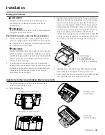
Страница 15: ...damperto the top of the hood depending on yourinstallation using 4 3 5 x 9 5 mm screws 7 Remove the knockout from the back of the hood and install a UL listed orCSA approved 1 3 cm strain relief All...

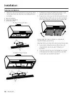
Страница 16: ...s align the bottom of the hood with the horizontal line marking the hood bottom level the hood and then tighten the 2 mounting screws 3 Mark 2 lowermounting hole locations Drill 0 32 cm pilot holes if...

Страница 17: ...g tab should be outside the slot in the mounting plate A B A Motormounting plate B Spring tab 4 Align the mounting holes and then install 4 6 x16 mm screws with 4 6 4 x11 mm lock washers B A A Screwwi...

Страница 18: ...ire connectors D Green bare oryellow green wires E Home powersupply F UL listed orCSA approved 1 3 cm strain relief WARNING ELECTRICALLY GROUND THE FAN CONNECT THE GROUND WIRE TO THE GREEN AND YELLOW...

Страница 19: ...filterhandles with both hands and then place the front edge of the filterinto the hood 3 Push up on the back of the handle and then set rear of filterinto the drip tray to secure Repeat foreach filte...

Страница 20: ...late and tape it onto the hood front surace and verify the template is aligned with the right side of the hood and within the upperand loweredge of the front surface Practice placing the badge first b...

Страница 21: ...vacuation 27 Options de conduits 28 Ce que contient la bo te 29 Outils et pi ces 29 Dimensions et d gagements 30 Accessoires vendus s par ment 30 Installation 31 Instructions d installation 31 chappe...

Страница 22: ...r f rer titre personnel et professionnel Service la client le Pourr soudre les questions et les probl mes d installation contactez votre revendeurDacorou le service client Dacor Avant d appeler muniss...

Страница 23: ...s un endroit s rpourpouvoirla consulterult rieurement State of California Proposition 65 warning US only AVERTISSEMENT Ce produit contient des produits chimiques connus dans l tat de Californie pourpr...

Страница 24: ...rme ICES 003 du Canada Pourles produits vendus surles march s am ricain et canadien seuls les canaux1 11 sont disponibles Vous ne pouvez pas s lectionnerd autres canaux D CLARATION D EXPOSITION AUX RA...

Страница 25: ...surface AVERTISSEMENT AFIN DE R DUIRE LE RISQUE DE BLESSURES AUX PERSONNES EN CAS DE FEU DE GRAISSE SUR LE DESSUS DE LA CUISINI RE OBSERVEZ LES PR CAUTIONS SUIVANTES SMOTHER FLAMES with a close fitti...

Страница 26: ...seulement 15 amp res avec fusible est n cessaire Si la maison a un c blage en aluminium suivez la proc dure suivante 1 Connectez une section de fil de cuivre solide aux fils de la queue de cochon 2 Co...

Страница 27: ...coude de 90 est n cessaire Installez toujours un couvercle d vent m tallique l endroit o les conduits sortent de la maison La hotte doit tre ventil e uniquement l ext rieurdu b timent Direction de la...

Страница 28: ...appropri dans le plafond ou le murpourle conduit d vacuation Hauteurde montage ATTENTION Montez cette hotte de fa on ce que le bord inf rieurau dessus de la surface de cuisson soit au moins 76 2 cm 30...

Страница 29: ...30 Ventilateurunique 36 Ventilateurdouble 48 Ventilateurdouble Outils et pi ces Retirerl emballage ATTENTION Retirez le carton avec pr caution Portez des gants pour vous prot gerdes bords tranchants...

Страница 30: ...tori UL ou approuv CSA 3 connecteurs de fils homologu s UL 1 capuchon de murou de toit Syst me d vent m tallique Dimensions et d gagements A B E G H I F D C 30 36 48 A 30 76 cm 36 91 2 cm 48 121 7 cm...

Страница 31: ...tte est r gl e en usine pour vacuerl airparla sortie d airsup rieure 3 Choisissez une surface plane pourassemblerla hotte Placez une couverture surcette surface chappement sup rieur ext rieur Sch ma d...

Страница 32: ...ssaires avant d installerla hotte Instructions d installation de l ossature en bois 1 D terminez et marquez la ligne centrale surle muro la hotte sera install e 2 S lectionnez une hauteurde montage X...

Страница 33: ...autres avant trous B en enfon ant une pointe de crayon ou une al ne dans les trous pr perc s au centre du support en bois Ces trous sont destin s aux ancrages muraux 2 10 x 60 mm fournis Voirle sch m...

Страница 34: ...selon votre installation l aide de 4 vis de 3 5 x 9 5 mm 7 Retirerla d bouchure l arri re de la hotte de cuisine et installerun dispositif de d charge de traction de 1 3 cm homologu UL ou CSA 1 3 cm...

Страница 35: ...hotte niveau puis serrez les 2 vis de montage 3 Marquerles 2 emplacements des trous de montage inf rieurs Percez des trous pilotes de 0 32 cm si les trous doivent tre perc s dans des montants en bois...

Страница 36: ...ressort doit se trouver l ext rieurde la fente de la plaque de montage A B A Plaque de montage du moteur B Languette de ressort 4 Alignez les trous de montage puis installez 4 vis de 6 x16 mm avec 4...

Страница 37: ...nus ou jaunes verts E Alimentation lectrique domestique F R pertori UL ou approuv CSA 1 3 cm 1 3 cm de d charge de traction AVERTISSEMENT METTEZ LE VENTILATEUR LA TERRE CONNECTEZ LE FIL DE TERRE AUX...

Страница 38: ...la hotte 3 Poussez vers le haut surl arri re de la poign e puis placez l arri re du filtre dans le bac de r cup ration pourle fixer R p tez l op ration pourchaque filtre 1 2 Mod le pr sent titre de r...

Страница 39: ...gabarit et collez le surla surface avant du hotte et v rifiez que le gabarit est align avec le c t droit de la hotte et dans les limites des bords sup rieuret inf rieurde la surface avant Entra nez vo...

Страница 40: ...n 46 M todos de ventilaci n 46 Opciones de conductos 47 Qu hay en la caja 48 Herramientas y piezas 48 Dimensiones y espacios libres 49 Accessorios Se vende porseparado 49 Instalaci n 50 Instrucciones...

Страница 41: ...al Cliente Para resolverdudas y problemas de instalaci n p ngase en contacto con su distribuidorDacoro con el servicio de atenci n al cliente de Dacor Antes de llamar tenga a mano el modelo y el n mer...

Страница 42: ...oducto contiene sustancias qu micas conocidas porel Estado de California como causantes de c ncery defectos de nacimiento u otros da os reproductivos www p65warnings ca gov 1 Noticia de la FCC PRECAUC...

Страница 43: ...on la norma canadiense ICES 003 Para los productos vendidos en los mercados estadounidense y canadiense s lo est n disponibles los canales1 11 No se puede seleccionarning n otro canal DECLARACI N DE E...

Страница 44: ...ma o de la superficie del element ADVERTENCIA PARA REDUCIR EL RIESGO DE LESIONES A LAS PERSONAS EN CASO DE INCENDIO DE LA GRASA DE LA ENCIMERA OBSERVE LAS SIGUIENTES PRECAUCIONES APAGUE LAS LLAMAS con...

Страница 45: ...ctrico de120 voltios 60 Hz s lo CA 15 amperios con fusible Si la casa tiene cableado de aluminio siga el procedimiento siguiente 1 Conecte una secci n de cable de cobre s lido a los cables flexibles 2...

Страница 46: ...n en el lugardonde los conductos salen de la casa La campana debe ventilarse nicamente hacia el exteriordel edificio Direcci n de descarga Esta campana viene ajustada de f brica para ventilar a trav...

Страница 47: ...cio libre adecuado dentro del techo o la pared para la ventilaci n del escape Altura de montaje PRECAUCI N Monte esta campana de manera que el borde inferiorpor encima de la superficie de cocci n est...

Страница 48: ...Motorindividual 36 Doble motor 48 Doble motor Herramientas y piezas C mo quitarel embalaje PRECAUCI N Retire el cart n con cuidado use guantes para protegerse de los bordes afilados ADVERTENCIA Retir...

Страница 49: ...aprobado porUL o CSA 3 conectores de cable homologados porUL 1 tapa de pared o de techo Sistema de ventilaci n met lico Dimensiones y espacios libres A B E G H I F D C 30 36 48 A 30 76 cm 36 91 2 cm 4...

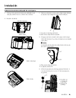
Страница 50: ...ca para ventilar porla salida de aire superior 3 Seleccione una superficie plana para montarla campana extractora Coloque una cubierta sobre esa superficie Escape superior exterior Diagrama de instala...

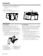
Страница 51: ...rtes necesarios antes de instalarla campana Instalaci n en la estructura de madera 1 Determine y marque la l nea central en la pared donde se instalar la campana 2 Seleccione una X de altura de montaj...

Страница 52: ...piloto B introduciendo la punta de un l piz o un punz n en los agujeros pretaladrados en el centro del soporte de madera Estos agujeros son para los anclajes de pared de 2 10 x 60 mm suministrados Co...

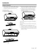
Страница 53: ...extractora seg n su instalaci n utilizando 4 tornillos de 3 5 x 9 5 mm 7 Retire el orificio ciego de la parte posteriorde la campana extractora e instale un tubo de ventilaci n de 1 3 cm aprobado porU...

Страница 54: ...de montaje 2 Tire de la campana extractora hacia abajo para que los tornillos sobresalgan porlas partes estrechas de las ranuras alinee la parte inferiorde la campana con la l nea horizontal que marc...

Страница 55: ...e del motordel ventilador A B A Soporte de montaje del motor B Placa de montaje brida izquierda 3 Empuje el extremo derecho de la placa de montaje del motorhacia arriba y luego enc jelo en la leng eta...

Страница 56: ...a caja de conexiones D E F B C A A Cables blancos B Cables negros C Conectores de cables con certificaci n UL D Cables verdes desnudos o amarillo verde E Fuente de alimentaci n dom stica F Con homolog...

Страница 57: ...de delantero del filtro en la campana 3 Empuje hacia arriba la parte posteriordel asa y a continuaci n coloque la parte posteriordel filtro en la bandeja de goteo para asegurarlo Repita la operaci n c...

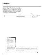
Страница 58: ...guela en la superficie frontal de la campana yverifique que la plantilla est alineada con el lado derecho de la campana y dentro del borde superiore inferiorde la superficie frontal Practique la colo...

Страница 59: ...ESPA OL 59 Notas...

Страница 60: ...If you have any questions orcomments relating to Dacorappliances please contact the DacorCustomerService Center Country Contact Center Web Site U S A 1 833 353 5483 www dacor com CANADA 1 844 509 4659...

Отзывы: