background image

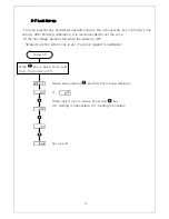
5-2. Function mode   


1)  How to set function. 


Measuring mode 

While 

  key is being 

Press, press 

  key 

END 

Содержание PDN-10

Страница 1: ...Ver 4 0 MODEL PDN 10 USER MANUAL DACELL CO LTD Address 681 1 Cheoksan Ri Nami Myeon Cheongweon Gun Chung buk TEL 82 43 260 2242 FAX 82 43 260 2245 http www dacell com E Mail info dacell com...

Страница 2: ...Front Panel 5 4 2 Features of Display Window 5 4 3 Connector Wiring Diagram 6 5 SET UP 7 5 1 Types of Setting mode Set up 7 5 2 Function mode Function Set up 8 5 3 Measuring DATA Saving and Transmitti...

Страница 3: ...features 1 1 Sigma Delta Conversion System It has middle high speed A D conversion equipment that detects input signal from sensor 100 times per second 1 2 Calibration System It has calibration syste...

Страница 4: ...ation please avoid a direct ray of light and dust Do not let this product contact with air including ion or salt Please do not use this product in the place with inflammable gas or steam or dust Pleas...

Страница 5: ...cations Available sensor DC Micor Voltage Output Sensor mV Strain Gauge Type Sensor Bridge 350 120 Maximum Display 19999 19999 Display Load Display 4 1 2 Digits LCD Status Display LED Red LED 3 Key Sw...

Страница 6: ...ta is in HOLD mode key Power on off It stays on when power key is pressed for 3 seconds key iThis key can be used to be out of Set up mode or to return to Measuring Mode as ESC Also it can be used to...

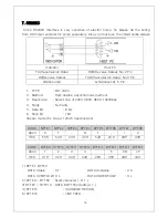
Страница 7: ...4 3 Connector Wiring Diagram LOAD CELL 5 pin connector 16 Communication RS232C 4 pin Connector 12 6...

Страница 8: ...setup mode Please refer 8 2 function mode Digital calibration mode It is to calibrate into the sensor s output value No need to prepare for the actual load stand weight Please refer 5 3 how to calibr...

Страница 9: ...5 2 Function mode 1 How to set function 8 Measuring mode While key is being Press press key END...

Страница 10: ...ndard set up value F 01 Decimal point 0 1 2 3 1 F 02 Division 1 2 5 10 20 50 1 F 03 Display filter 4 8 16 32 16 F 04 Hold mode Sample hold Peak hold Absolute peak hold Peak hold F 09 ID Number 0 32 1...

Страница 11: ...20 40 60 50 Displayed in 50 0 50 100 150 F 03 Display filter Display speed setup Standard setup value 16 Display data Setting 0 No filter 4 Average time 1 8 sec 8 Average time 1 4 sec 16 Average time...

Страница 12: ...ot set up Stream mode always transmit data 32 01 32 Device number is set up Command mode Transmit data by command F 10 Baud rate Print Communication Speed Print Setup Standard setup value 9 60 Display...

Страница 13: ...press KEY to save and escape You can save from A001 to A500 2 DATA Search Please press KEY and then on display window And you can select address by using and KEY Please press KEY in the selected addr...

Страница 14: ...be used for the calibration for easier calibration and key And then Press key 13 Measuring mode While key is being Press press key Display Function mode Display Sensor output value calibration mode Di...

Страница 15: ...ion mode Display Actual load calibration mode Display actual load mode Input the rated output value by using and key And then Press key Calibration end Display zero mode press key without any load on...

Страница 16: ...ey is being Press press key Display Function mode Display Sensor output value calibration Display Actual load calibration indicate Input the rated output value by using and key And then Press key Cali...

Страница 17: ...set the Lock At the first stage please start while the power is OFF Related Function when Lock is set Function related to calibration Power off While key is being Press and then the power is ON Pleas...

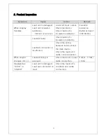
Страница 18: ...le Case 1000 Mohm Loadcell faulty Check load cell s insulation resistance Loadcell connection is insufficient Check the wiring between load cell and the main device Check the load cell s calbe s disco...

Страница 19: ...3 Baud rate Select one of 2400 4800 9600 19200bps 4 Parity No Parity 5 Data bit 8 bit 6 Stop bit 1bit Stream mode Ex Data 1234 5 transmission CODE BYTE1 BYTE2 BYTE3 BYTE4 BYTE5 BYTE6 BYTE7 BYTE8 ASCII...

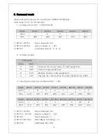
Страница 20: ...e of order equipment H 48H Hold for order equipment R 52H Release hold for order equipment Z 5AH Operate the current value of order equipment as ZERO 3 Transmission DATA form INDICATOR PC CODE BYTE1 B...

Страница 21: ...command U 55H Transfer since Save Data command EX A001P AD001 AD500 A005D AD001 AD005 A050U AD050 AD500 3 Transmission Data Form INDICATOR PC CODE BYTE1 BYTE2 BYTE3 BYTE4 BYTE5 BYTE6 BYTE7 BYTE8 ASCI...

Отзывы: