background image

3

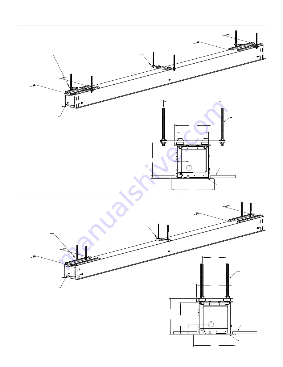
Suggested Methods of Installation

Method 1

Method 2

Adjustable 

Mounting Nuts

Motor 
End

Electrical 

Junction Box

15½"

[39.4cm]

Fixed 

Mounting 

Nuts

Audience Side

15½"

[39.4cm]

NOTE:

 For method 2 threaded rod must be 5/16-18 thread.

Variable Position 

Mounting Bracket

Motor 
End

Electrical 

Junction Box

15½"

[39.4cm]

Fixed 

Bracket

Audience Side

15½"

[39.4cm]

9¼"

[23.5 cm]

5¾"

[14.6cm]

5"

[12.6cm]

5¾" [14.6cm]

2"

[4.8cm]

15/8" [4.2cm]

6¾"

[17.2cm]

3/8" Threaded Rod 

(Not Included)

Attached to 

Mounting Bracket

Finished Ceiling

Self-Trimming 

Flange

4"

[10 cm]

5¾"

[14.6cm]

51/8" 

[13.1cm]

5¾" 

[14.6cm]

15/8" [4.2cm]

6¾"

[17.2cm]

Finished Ceiling

Self-Trimming 

Flange

5/16" Threaded 

Rod (Not 

Included)

Attached to 

Mounting Nut

Содержание DescenderPro

Страница 1: ...INSTRUCTION BOOK FOR DescenderPro ...

Страница 2: ...he supply cord is damaged it must be replaced by the manufacturer its service agent or similarly qualified persons in order to avoid hazard 7 Supplied drive is only intended for use in Da Lite screen models Advantage Contour and Cosmopolitan 8 Position the cord so that it will not be tripped over pulled or contact hot surfaces 9 If an extension cord is necessary a cord with a current rating at lea...

Страница 3: ...able Position Mounting Bracket Motor End Electrical Junction Box 15 39 4cm Fixed Bracket Audience Side 15 39 4cm 9 23 5 cm 5 14 6cm 5 12 6cm 5 14 6cm 2 4 8cm 15 8 4 2cm 6 17 2cm 3 8 Threaded Rod Not Included Attached to Mounting Bracket Finished Ceiling Self Trimming Flange 4 10 cm 5 14 6cm 51 8 13 1cm 5 14 6cm 15 8 4 2cm 6 17 2cm Finished Ceiling Self Trimming Flange 5 16 Threaded Rod Not Include...

Страница 4: ...n 2 Tighten bolts until trim flange is flush with ceiling NOTE For proper operation case must be levelled side to side and front to back 3 Loosen screw using a 2 Phillips screwdriver to slide junction box door and rotate open Install electrical connections that apply to your unit Make sure to review the wiring diagram for proper hook up Close junction box by rotating lid and sliding over screw Sec...

Страница 5: ... screwdriver through motor and pin end bracket Figure 4 7 Install access door Slide motor end of door onto mounting post Figure 5 Lift up slat on pin end side and hook door onto pin end mounting post Figure 6 8 Rotate access door upward and push until you hear springs latch into door bracket Figure 7 There are three attachment points motor end pin end and center NOTE If the center latch does not e...

Страница 6: ...uge wire can be used in place of the supplied RJ 14 cable to connect the wall switch Connect the BUS terminals on the wall switch to the corresponding BUS terminals on the splitter board UP STOP DOWN BUS COM 5V Power Input 120VAC 60Hz Green Ground Ground Must be Connected to Building Ground Black Hot White Common Power Wire Data Cable RJ 45 Jack RJ 22 Jack Connection to Wall Switch RJ 22 Jack RJ 1...

Страница 7: ...e Brown 230V Wiring Diagram with Operation Limit Adjustment Wall Switch 3 conductor 20 24 gauge wire can be used in place of the supplied RJ 14 cable to connect the wall switch Connect the BUS terminals on the wall switch to the corresponding BUS terminals on the splitter board IMPORTANT NOTE The wall switch is REQUIRED to make any limit switch adjustments EVEN if a third party control system is u...

Страница 8: ... operation only and CANNOT be used to make limit switch adjustments Therefore it is advised to wire the limit adjustment switch or provide a 3 conductor connection that is accessible Power Input 230VAC 50Hz Green Yellow Ground Blue Hot Brown Common Power Wire Data Cable RJ 45 Jack Black Down White Common Red Up Red Black White Inputs Output Black Down White L Common Red Up Push Down on Tab to Inse...

Страница 9: ...mit switch press and hold the up tactile button until the LED on the back of the switch turns solid green This will put the motor in limit set mode Turn the wall switch over and use the up button on the front of the switch Press and hold the up button until the desired up position is reached If you travel too far up press the down button to move the screen downward If you press and let go of eithe...

Страница 10: ...ure across the common up and down wires will be a stop command Operation of Screen Operation Limit Adjustment Wall Switch 1 Press DOWN button on screen switch and screen will deploy out of case in downward direction 2 Press STOP button on screen switch and screen will stop if in movement 3 Press UP button on screen switch and screen will retract upward into case Up Button Stop Button Down Button U...

Страница 11: ... See Screen Adjustment section Noise NOTE Screen will operate with a low pitched hum Squeaking rubber end plug rubbing on motor Center roller in case Grinding Foreign object in screen rubbing on roller or fabric Remove Gear noise Replace motor assembly Coasting Defective brake Replace motor assembly Fabric hangs crooked Screen not installed properly Check for level and plumb Fabric has backed up i...

Страница 12: ...ies of fitness for use or merchantability that may be mandated by statute or rule of law are limited to the five 5 year warranty period This warranty gives you specific legal rights and you may also have other rights which vary from state to state TO THE MAXIMUM EXTENT PERMITTED BY APPLICABLE LAW NO LIABILITY IS ASSUMED FOR EXPENSES OR DAMAGES RESULTING FROM INTERRUPTION IN OPERATION OF EQUIPMENT ...

Отзывы: