background image


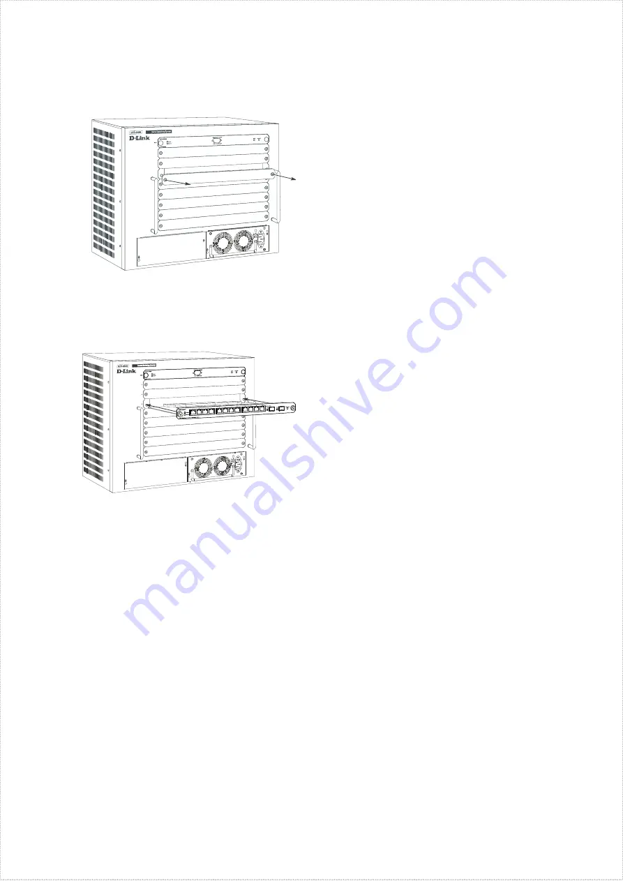
1.  Remove a blank slot cover. 


2.  Carefully slide a module into the slot, making 

sure that its sides are inside the guide rails. 


3.  When the module reaches the back of the chassis, 

push gently but firmly to connect the rear sockets 
of the module to the back-plane. Ensure that the 
module  is  completely  inserted  into  the  chassis 
such  that  its  front  panel  is  flush  with  the  front 
panel of the chassis. 

4.  Tighten  the  two  large  module  screws  to  ensure 

that the module is held firmly in place. 


Note:

  Networking  modules  are  hot-swappable, 

meaning they can be added and removed while power 
to  the  switch  is  ON.  The  CPU  module  however,  is 
NOT  hot-swappable.  Removing  or  inserting  the  CPU 
module  while  the  power  is  on  may  cause  irreparable 
damage  to  the  module  and/or  to  the  switch  itself. 
Further,  make  sure  you  have  unplugged  the  power 
cord from the removable power supply module before 
inserting or removing it from the switch. 
 

CAUTION:  Due  to  the  high  energy  present 

in  this  system,  extreme  caution  should  be 

exercised  whenever  adding  or  removing 

system  components.  No  element  of  this 

system  may  be  installed  or  removed  except 

by an authorized technician. 

Step 4 – Plugging in the AC Power Cord 

At this point, please connect the AC power cord into an 
electrical  outlet  (preferably  one  that  is  grounded  and 
surge  protected)  and  into  a  redundant  power  supply 
module in the switch. 

Step 5 – Connecting a Console 

In order to setup and manage the switch, you will need 
to connect a console terminal. A console can be either a 
dedicated management terminal such as a VT-100 or a 
PC  using  a  terminal  emulation  program  such  as 
Microsoft  HyperTerminal,  which  is  automatically 
installed on a system when Windows is installed. 

Regardless  of  the  type  of  management  station  you  are 
using,  the  RS-232  console  included  with  the  switch 
must be used to make the console connection. 

At  this  point,  plug  the  9-pin  connector  of  the  console 
cable to the serial port on the rear of your terminal or 
PC  and  the  9-pin  connector  into  the  RS-232  Console 
port  on  the  front  panel  of  the  CPU  module  located  in 
the top slot in the switch. 

If you are using a PC, please locate and run a terminal 
emulation program. 

The terminal should be configured to these settings: 


Bits per second

 --- 115200 


Data bits

 --- 8 


Parity

 --- None 


Stop bits

 --- 1 


Flow Control

 --- None 

After  you  have  plugged  in  power  to  the  switch, 
connected  the  console  and  run  a  terminal  emulation 
program,  you  should  see  the  switch  console 
management login screen. If you do not see the screen, 
hit <Ctrl>  +  R,  to  refresh  the  screen.  The  login  screen 
should now appear. 

To  logon  to  the  switch,  press  <Enter>  or  <Return>  in 
the username and password fields. 

Additional Information 

For  more  information  setting  up  your  network  or 
configuring the switch, please refer to the User’s Guide 
located  on  the  CD-ROM.  It  contains  many  more  rules, 
charts, explanations and examples to help you get your 
network up and running. 

Содержание TM DES-6500

Страница 1: ...brackets have been secured use the screws provided with the equipment rack to mount the switch on the rack Step 3 Installing Modules The DES 6500 ships as a base unit which includes DES 6501 Backplane Chassis provides electrical power to and conveys transmissions between modules DES 6502 CPU Module Switching and management module located in the uppermost slot DES 6511 Redundant Power Supply Module...

Страница 2: ... in the switch Step 5 Connecting a Console In order to setup and manage the switch you will need to connect a console terminal A console can be either a dedicated management terminal such as a VT 100 or a PC using a terminal emulation program such as Microsoft HyperTerminal which is automatically installed on a system when Windows is installed Regardless of the type of management station you are u...

Страница 3: ...tates and http www dlink co uk for Great Britain URLs for D Link Websites in other countries are contained in the list of D Link Offices at the back of the User s Guide Einführung Diese Kurzanleitung hilft Ihnen Schritt für Schritt bei der Installation des DES 6500 von D Link ...

Страница 4: ...ten haben Schritt 3 Module installieren Das DES 6500 wird als Grundeinheit geliefert und umfasst DES 6501 Backplane Gehäuse dient der Stromversorgung und der Übertragung zwischen den Modulen DES 6502 CPU Modul Switching und Management Modul im obersten Steckplatz DES 6511 Redundantes Stromversorgungsmodul in einem der beiden größeren Steckplätze unter dem Switch Folgende Netzwerkmodule sind zusätz...

Страница 5: ... Stromversorgung anschließen Verbinden Sie das Netzkabel mit einer Steckdose wenn möglich geerdet und mit Überspannungsschutz und mit einem redundanten Stromversorgungsmodul im Switch Schritt 5 Konsole anschließen Zum Einrichten und Verwalten des Switch müssen Sie ein Konsolenterminal anschließen Dies kann entweder ein spezielles Verwaltungsterminal sein z B VT 100 oder ein PC mit Terminalemulatio...

Страница 6: ... und Inbetriebnahme Ihres Netzwerks unterstützen Weitere Hilfe ist im Internet verfügbar unter http www dlink com USA und http www dlink co uk Großbritannien Die Adressen der Webseiten von D Link in anderen Ländern finden Sie in der Liste der D Link Niederlassungen auf der Rückseite des Benutzerhandbuchs Introduction Ce Guide d installation rapide vous donne des instructions détaillées pour l inst...

Страница 7: ...our monter le switch sur le rack Etape 3 Installation des modules Le DES 6500 est livré sous forme d unité de base comprenant Châssis de plan arrière DES 6501 assure l alimentation électrique et les transmissions entre modules Module CPU DES 6502 Module de commutation et de gestion situé dans la fente du haut Module d alimentation électrique redondante DES 6511 situé dans l une des grandes fentes ...

Страница 8: ...veuillez brancher le cordon d alimentation AC dans une prise électrique de préférence une prise reliée à la terre et protégée contre les surtensions et dans un module d alimentation électrique redondante du switch Etape 5 Branchement d une console Pour installer et gérer le switch vous devez connecter un terminal de console Une console peut être soit un terminal de gestion dédié tel qu un VT 100 o...

Страница 9: ...des croquis des explications et des exemples pour vous aider à faire fonctionner votre réseau Vous pouvez obtenir une aide complémentaire sur http www dlink com pour les Etats Unis ou http www dlink co uk pour la Grande Bretagne Les URL des sites web de D Link dans les autres pays sont indiqués dans la liste des bureaux D Link qui figure au dos du Guide d utilisation Introducción Esta Guía rápida ...

Страница 10: ...los módulos El DES 6500 es una unidad base que incluye DES 6501 Chasis backplane Proporciona alimentación eléctrica a los módulos y conduce las transmisiones entre ellos DES 6502 Módulo CPU Módulo conmutador y de gestión situado en el slot superior DES 6511 Módulo fuente de alimentación redundante Situado en la parte inferior del conmutador en uno de los slots grandes Los módulos de red que se ven...

Страница 11: ...toma de tierra y con protección de sobretensión y en un módulo fuente de alimentación redundante del conmutador Paso 5 Conexión de una consola Para configurar y gestionar el conmutador es necesario conectar un terminal consola Una consola puede ser un terminal dedicado a la gestión como un VT 100 o un PC que utilice un programa emulador de terminal como Microsoft HyperTerminal que se instala autom...

Страница 12: ...cluye más indicaciones gráficos explicaciones y ejemplos que le ayudarán a configurar la red y a ponerla en funcionamiento También puede encontrar más información en http www dlink com para Estados Unidos y en http www dlink co uk para Gran Bretaña Las direcciones web D Link para otros países figuran en la lista de delegaciones D Link al final de la Guía del usuario ...

Страница 13: ...fe montare lo switch all interno del rack utilizzando le viti fornite con il rack stesso Fase 3 Installazione dei moduli Il dispositivo DES 6500 viene fornito come unità base che include Backplane Chassis DES 6501 fornisce l alimentazione elettrica e gestisce la trasmissione tra moduli Modulo CPU DES 6502 modulo di commutazione e gestione ubicato nello slot superiore Modulo di alimentazione ridond...

Страница 14: ...ntazione ridondante dello switch Fase 5 Connessione alla console Per la configurazione e la gestione dello switch è necessario connettere un terminale console La console può essere un terminale di gestione dedicato come un terminale VT 100 o un PC dotato di un programma di emulazione come Microsoft HyperTerminal presente su tutti i sistemi dotati di sistema operativo Windows Indipendentemente dal ...

Страница 15: ...in opera della rete Ulteriori informazioni sono disponibili online all indirizzo http www dlink it per l Italia Gli indirizzo dei siti D Link degli altri paesi sono contenute nell elenco degli uffici D Link riportato nell ultima pagina del Manuale utente Введение В данном Руководстве по быстрой установке приведены пошаговые инструкции по установке коммутатора D Link ...

Страница 16: ...екта Затем используя винты от стойки прикрепите к ней коммутатор Шаг 3 Установка модулей DES 6500 допускает установку следующих модулей DES 6501 Backplane Chassis объединительный блок обеспечивает электропитание модулей и их взаимодействие DES 6502 CPU Module модуль коммутации и управления устанавливается в самый верхний слот DES 6511 Redundant Power Supply Module резервный источник питания устана...

Страница 17: ...ючите кабель питания к розетке сети питания желательно к заземленной и защищенной от перепадов напряжения и к резервному источнику питания коммутатора Шаг 5 Подключение консоли Чтобы получить возможность настраивать коммутатор и управлять им необходимо подключить консольный терминал Консолью может быть как выделенный терминал управления такой как VT 100 так и ПК использующий программу эмуляции тер...

Страница 18: ...коммутатора пожалуйста обращайтесь к Руководству пользователя на CD ROM В нем содержится перечень правил схемы пояснение многих понятий и примеры помогающие настроить и запустить в эксплуатацию сеть Дополнительная информация доступна на сайте http www dlink ru Ссылки на Web сайты D Link в других странах содержатся в списке офисов D Link в конце Руководства пользователя ...

Страница 19: ... 本 本 本 本 本 本 本 本 本 3 DES 6500 本 本 本 本 本 DES 6501 桌 桌 桌 桌 本 本 本 本 本 本 本 本 本 本 本 本 本 本 本 DES 6502 CPU 桌 桌 本 本 本 本 本 本 本 本 本 本 本 本 本 本 本 本 本 DES 6511 本 本 本 本 本 本 本 本 本 本 本 本 本 本 本 本 本 本 本 本 本 本 本 本 本 本 本 本 本 本 本 本 本 本 本 本 本 本 DES 6502 CPU 本 本 DES 6504 12 本 100BASE FX SFF 本 本 本 本 本 本 本 本 本 本 本 DES 6505 8 本 1000BASE SX SC Gigabit 本 本 本 本 本 本 本 本 本 DES 6506 24 本 RJ45 Patch Panel 本 本 DES 6507 12 本 1000BA...

Страница 20: ...本 本 本 本 本 本 本 本 本 本 本 本 本 本 本 VT 100本 本 本 本 本 本 本 本 本 本 本 本 本 本 本 本 Microsoft HyperTerminal 本 本 本 本 本 本 Windows 本 本 本 本 本 本 本 本 本 本 本 本 本 本 本 本 本 本 本 本 本 本 本 本 本 本 本 本 本 本 本 RS 232 本 本 本 本 本 本 本 本 本 本 本 本 9 pin 本 本 本 本 本 本 本 本 本 本 本 本 本 PC 本 本 本 本 本 本 本 本 本 本 本 本 本 本 本 本 本 本 本 本 本 本 本 CPU 本 本 本 本 本 本 RS 232 本 本 本 本 本 本 本 PC本 本 本 本 本 本 本 本 本 本 本 本 本 本 本 本 本 本 本 本 本 本 本 本 本 Bits per second 115200 Da...

Отзывы: