background image

3

E

N

G

LIS

H

Rack Installation

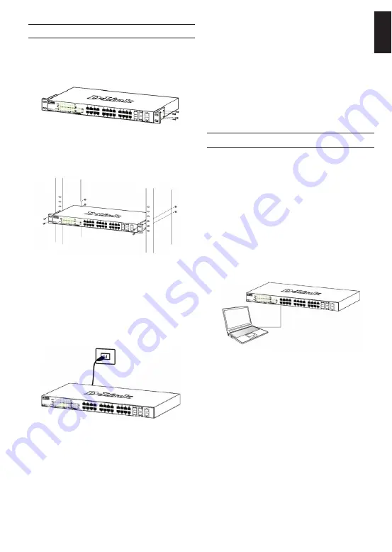
The switch can be mounted in an EIA standard size 

19-inch rack, which can be placed in a wiring closet with 

other equipment. To install, attach the mounting brackets 

to the switch’s side panels (one on each side) and 

secure them with the screws provided.

Figure 3. Attaching the mounting brackets

Then, use the screws provided with the equipment rack 

to mount the switch in the rack.

Figure 4.   Installing the switch in a standard-sized 

equipment rack

Step 3 – Plugging in the AC 

Power Cord

You can now connect the AC power cord into the rear of 

the switch and to an electrical outlet (preferably one that 

is grounded and surge protected).

Figure 5. Plugging the switch into an outlet

Power Failure

As a precaution, the switch should be unplugged in 

case of power failure. When power is resumed, plug the 

switch back in.

Management Options

Web-based Management Interface

After a successful physical installation, you can configure 

the switch, monitor the LED panel, and display statistics 

graphically using a web browser, such as Microsoft

®


Internet Explorer version 7.0 and higher, Firefox, Chrome 

or Safari.
You need the following equipment to begin the web 

configuration of your device:

• 

 A PC with a RJ-45 Ethernet connection

• 

 A standard Ethernet cable

Step 1

Connect the Ethernet cable to any of the ports in front 

panel of the switch and to the Ethernet port on the PC.

Figure 6. Connected Ethernet cable

This system may be managed out-of-band through the 

console port on the front/back panel or in-band using 

Telnet. The user may also choose the web-based 

management, accessible through a web browser. Each 

Switch must be assigned its own IP Address, which is 

used for communication with an SNMP network manager 

or other TCP/IP application (for example BOOTP, TFTP). 

The Switch’s default IP address is 10.90.90.90. The user 

can change the default Switch IP address to meet the 

specification of your networking address scheme.

Содержание SmartPro DGS-1510-52XMP

Страница 1: ...2 с 48 портами 10 100 1000Base T и 4 портами 10GBase X SFP 48 портов с поддержкой PoE 802 3af 802 3at 30 Вт PoE бюджет 370 Вт 740 Вт при использовании внешнего источника питания DPS 700 Getting Started Guide Layer 2 SmartPro Stackable Switch with 48 10 100 1000Base T PoE Ports and 4 10GBase X SFP Ports ...

Страница 2: ...ched on the bottom at each corner of the device s base Allow enough ventilation space between the device and the objects around it Figure 1 Attaching the rubber feet Grounding the Switch depending on the purchased model This section describes how to connect the Switch to ground You must complete this procedure before powering on your Switch Required Tools and Equipment Grounding screws included in...

Страница 3: ...Management Interface After a successful physical installation you can configure the switch monitor the LED panel and display statistics graphically using a web browser such as Microsoft Internet Explorer version 7 0 and higher Firefox Chrome or Safari You need the following equipment to begin the web configuration of your device A PC with a RJ 45 Ethernet connection A standard Ethernet cable Step ...

Страница 4: ...the DNA you can find it under Start Programs D Link DNA 5 Just connect the Switch to the same L2 network segment of your PC and use the DNA D Link Network Assistant to discover the Switches Option 2 Follow these steps to install the DNA D Link Network Assistant manually 1 Insert the Utility CD into your CD Rom Drive 2 From the Start menu on the Windows desktop choose Computer 3 Double click on you...

Страница 5: ...at a valid connection is made through the Ethernet port of the Switch and your PC and then click Start Programs Accessories Command Prompt on your computer Once the console window opens enter the command telnet 10 90 90 90 depending on configured IP address and press Enter on your keyboard You should be directed to the opening console screen for the Command Line Interface of the 1 Connect the RS 2...

Страница 6: ...ствовать параметрам электропитания указанным в технических характеристиках устройства Не вскрывайте корпус устройства Перед очисткой устройства от загрязнений и пыли отключите питание устройства Удаляйте пыль с помощью влажной салфетки Не используйте жидкие аэрозольные очистители или магнитные статические устройства для очистки Избегайте попадания влаги в устройство Устройство должно также быть за...

Страница 7: ...беспечьте достаточное пространство для вентиляции между устройством и объектами вокруг него Рисунок 1 Крепление резиновых ножек Заземление коммутатора Данный раздел содержит информацию о способе заземления коммутатора Данную процедуру необходимо выполнить перед включением питания коммутатора Необходимые инструменты и оборудование Винт заземления M4 x 6 мм входит в комплект для монтажа Провод зазем...

Страница 8: ...ожно управлять локально через консольный порт на передней панели либо удаленно используя Telnet Пользователь также может управлять коммутатором через Web интерфейс посредством Web браузера Каждому коммутатору должен быть назначен IP адрес который используется для взаимодействия с сетевым менеджером SNMP или другими приложениями TCP IP например BOOTP TFTP IP адрес коммутатора по умолчанию 10 90 90 ...

Страница 9: ... Подключение к консольному порту Для подключения к консольному порту необходимо использовать специальный консольный кабель Данный кабель оснащенный разъемами RS 232 и RJ 45 входит в комплект поставки Для подключения к консольному порту коммутатора выполните следующее 1 Подключите кабель разъемом RS 232 к консольному порту компьютера 2 Подключите кабель разъемом RJ 45 к консольному порту коммутатор...

Страница 10: ...основе Telnet Пользователи могут также получить доступ к коммутатору через Telnet с помощью командной строки Для доступа с компьютера пользователя прежде всего необходимо убедиться в наличии соединения коммутатора с компьютером через порт Ethernet Затем нажмите Start Пуск Programs Программы Accessories Стандартные Command Prompt Командная строка В окне консоли введите команду telnet 10 90 90 90 в ...

Страница 11: ...атура От 5 до 50 C o Температура хранения От 20 до 70 C o Влажность при эксплуатации От 0 до 95 без конденсата EMI CE FCC C Tick VCCI BSMI CCC Безопасность cUL CB MTBF часы 303 027 Тепловыделение 1 660 33 БТЕ час Уровень шума При высокой скорости вентилятора 55 4 дБ При низкой скорости вентилятора 49 3 дБ Система вентиляции 4 вентилятора Smart Вес 5 41 кг Влажность при хранении От 0 до 95 без конд...

Страница 12: ...495 744 00 99 E mail mail dlink ru Україна Київ вул Межигірська 87 А Тел 38 044 545 64 40 E mail ua dlink ua Moldova Chisinau str C Negruzzi 8 Tel 373 22 80 81 07 E mail info dlink md Беларусь Мінск пр т Незалежнасці 169 Тэл 375 17 218 13 65 E mail support dlink by Қазақстан Алматы Құрманғазы к cі 143 үй Тел 7 727 378 55 90 E mail almaty dlink ru Հայաստան Երևան Դավթաշեն 3 րդ թաղամաս 23 5 Հեռ 374 1...

Отзывы: