background image


DSN-4000 Series Hardware Reference Guide 


23 

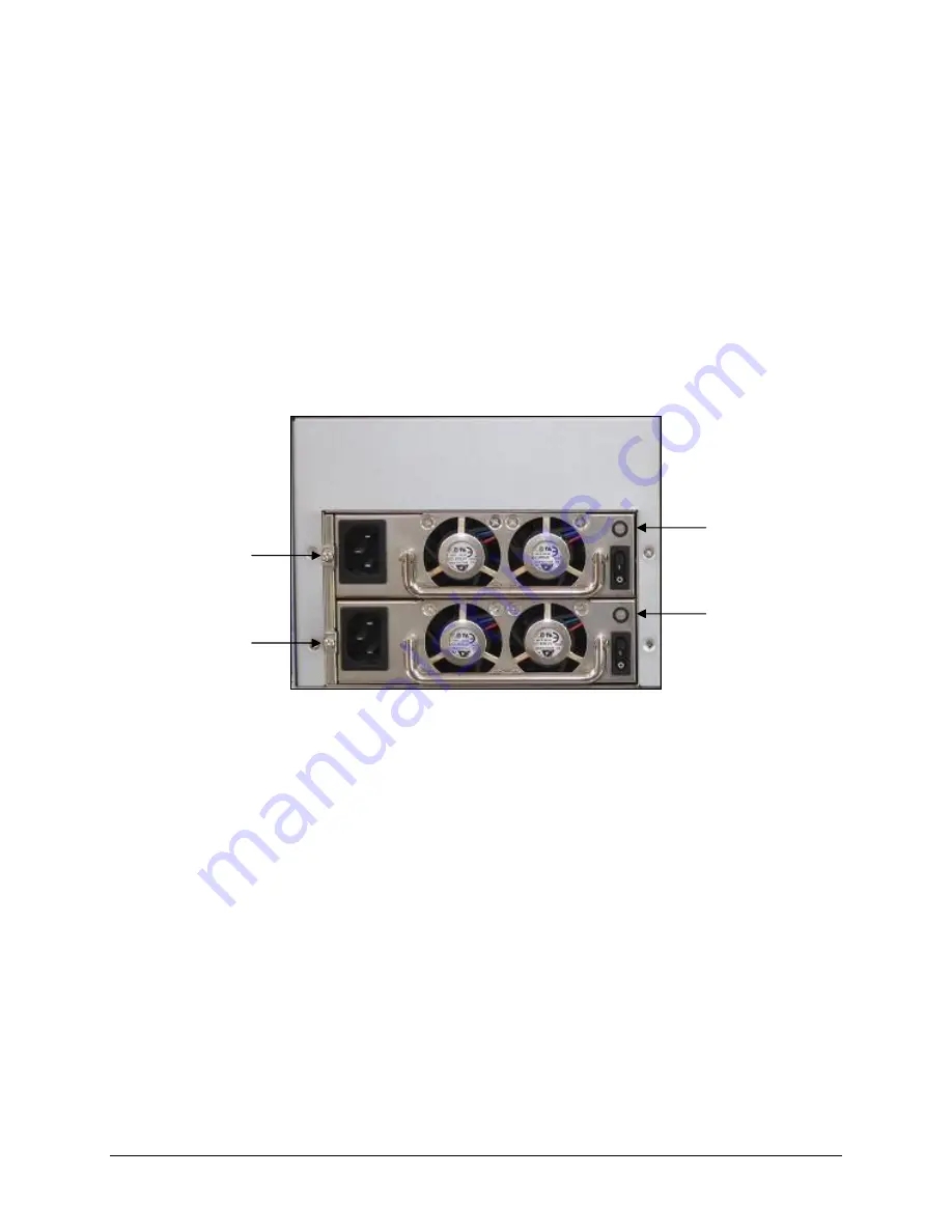
A.2  Replacing a Power Supply Module 

The redundant power supplies on the DSN-4000 series are field-replaceable units.  You can 
replace a power supply module without removing the enclosure from the rack. 

To remove the power supply module: 

1.


Verify that the power supply LED is amber or red. 

2.


Switch off the power to the power supply module you plan to replace. 

3.


Unplug the power cord. 

4.


Loosen and remove the retaining screw on the left side of the power supply module. 

5.


Pull the power supply module out of the DSN-4000 series enclosure. 


Figure A-1. Removing a Power Supply Module 

To install the replacement power supply: 

1.


Carefully slide the power supply module into the DSN-4000 series enclosure. 

2.


Install and tighten the retaining screw on the left side of the power supply. 

3.


Plug in the power cord. 

4.


Switch on the power supply. 

5.


Verify that the new power supply LED is green. 


Retaining Screw for 

Power Supply #0 

Retaining Screw for 

Power Supply #1 

Status LED for 

Power Supply #0 

Status LED for 

Power Supply #1 

Содержание DSN-4100 Series

Страница 1: ...D Link xStack Storage iSCSI SAN Array Managed SAN Solution DSN 4100 DSN 4200 and DSN 4000 Hardware Reference Guide Version 1 0 xStack Storage TM ...

Страница 2: ...ii ...

Страница 3: ...nd Trademark Office All other product names mentioned herein may be trademarks or registered trademarks of their respective companies Microsoft Windows is a U S registered trademark of Microsoft Corporation All other brand or product names are or may be trademarks or service marks and are used to identify products or services of their respective owners Important data protection information You sho...

Страница 4: ...nt type recommended by the manufacturer Do not dispose of the battery along with household waste Contact your local waste disposal agency for the address of the nearest battery disposal site CAUTION RISK OF EXPLOSION IF BATTERY IS REPLACED BY AN INCORRECT TYPE DISPOSE OF USED BATTERIES ACCORDING TO THE INSTRUCTIONS Notice of Export Controls Export of technical data contained in this document may r...

Страница 5: ...illustrations may only show the DSN 4200 enclosure but the concepts are applicable to all models Typographic Conventions Notes Notes provide information that deserves special attention They are preceded by Cautions Cautions contain information which if not followed can cause damage to the storage system and possible loss of data They are preceded by Warnings Warnings contain information which if n...

Страница 6: ... or by phone Tech Support for customers within the United States D Link Technical Support over the Telephone Please see our support site for current number http support dlink com Monday to Friday 8 00am 5 00pm PST PDT D Link Technical Support over the Internet http support dlink com Tech Support for customers within Canada D Link Technical Support over the Telephone Please see our support site for...

Страница 7: ...y the User 14 3 5 Installing the Hard Disk Drives 15 3 6 Connecting to the iSCSI Data Ports 16 3 7 Connecting to the Management Port 16 3 8 Connecting the AC Power Cords 18 3 9 Connect any DSN 4000 JBOD Expansion Arrays optional 18 3 10 Powering on the DSN 4000 JBOD Expansion Arrays 19 3 11 Powering on the DSN 4X00 Storage Array 20 3 12 Hot Plugging Additional DSN 4000 JBOD Expansion Arrays 20 App...

Страница 8: ...viii Contents This page intentionally left blank ...

Страница 9: ...d SCSI SAS or Serial Advanced Technical Attachment SATA hard disk drives per system including DSN 4000 expansion arrays with a maximum storage capacity of 2TB per drive A minimum of 512 MB of System Memory expandable to 2GB A minimum of 1024 MB of Buffer Memory expandable to 4 GB iSCSI Ethernet Connectors depending on your specific hardware configuration Eight 1 Gigabit RJ 45 connectors Four 1 Gig...

Страница 10: ...ve costs Scalability over long distances ideal for remote data replication and disaster recovery High availability redundant cooling fans and 2 redundant hot swappable auto sensing load sharing power supplies Intelligent battery pack ensures that a charged battery is on hand to preserve buffer cache contents if a power failure occurs Contents are backed up for approximately 72 hours with the stand...

Страница 11: ... Series Primary Array Layout This chapter describes the hardware components on the DSN 4X00 primary array The topics covered in this chapter are Section 2 1 Front Panel Components Section 2 2 Rear Panel Components Section 2 3 Side Top and Bottom Panel Components ...

Страница 12: ... model as shown in Figure 2 4 Drive Carriers hard disk drives are mounted on a drive carrier for easy insertion or removal The drive carriers have a squeeze lever for installing and removing drives and two status LEDs see Figure 2 3 and Table 2 2 Each drive carrier has a corresponding drive slot number see Figure 2 4 Drive carriers must be installed in all drive slots that are not occupied by a ha...

Страница 13: ...t Flashing Green While the system is operating normally this LED blinks seven 7 times then turns off for approximately 4 seconds then repeats with a total cycle time of 8 seconds Figure 2 3 Detailed View of the Drive Carrier Table 2 2 Drive Carrier Status LEDs LED Description Disk Status Off No hard disk is present Green The hard disk is powered on and available Red The hard disk has failed and sh...

Страница 14: ... to the right of the iSCSI data ports This connector allows you to attach additional DSN 4000 JBOD expansion arrays to the primary array to increase the system s total storage capacity see Section 3 9 for more information RESET button is located above the SAS Expansion port This button allows you to explicitly restart the system For more information refer to Table 2 5 MUTE button is located above ...

Страница 15: ...hing Amber Data is being sent or received Off No data is being sent or received Link Speed Green Network link is operating at 1000 Mbps Red Network link is operating at 100 Mbps Off No network link is detected Reset Button Mute Audio Alarm Button Battery and Fan Status LEDs Dirty Cache LED Management Port Controller Status LED RS 232 Serial Diagnostic Port Hot Swappable Fan Module Hot Swappable Fa...

Страница 16: ... controller is operating normally Red The controller encountered a failure condition that requires some corrective action Off The controller is powered off or not ready Dirty Cache Flashing Green The battery is maintaining cache memory when the system is powered off or when a system fault condition has occurred Off The cache memory is functioning normally Battery Status Solid Green The battery is ...

Страница 17: ...ll sound A system shutdown and restart are required after the failed battery has been replaced Over Temperature The Global Enclosure Status LED and Controller Status LED will be illuminated in red and the audio alarm will sound Software Failure The Global Enclosure Status LED and Controller Status LED will be illuminated in red and the audio alarm will sound 2 3 Side Top and Bottom Panel Component...

Страница 18: ...10 Chapter 2 VessRAID 1836i 1846i Series Primary Array Layout This page intentionally left blank ...

Страница 19: ...iderations Section 3 3 Unpacking the DSN 4X00 Primary Array Section 3 4 Items Supplied by the User Section 3 5 Installing the Hard Disk Drives Section 3 6 Connecting to the iSCSI Data Ports Section 3 7 Connecting to the Management Port Section 3 8 Connecting the AC Power Cords Section 3 9 Connect any DSN 4000 JBOD Expansion Arrays optional Section 3 10 Powering on the DSN 4000 JBOD Expansion Array...

Страница 20: ...the two power outlets should be on separate circuits for optimum power redundancy The location should allow for at least six inches 15 2 cm of space at the front and back of the DSN 4X00 storage array for ventilation Do not place the DSN 4X00 storage array next to on top off or below any device that generates a significant amount of heat or will block the free flow of air through the DSN 4X00 stor...

Страница 21: ...y grounded To ensure the integrity of the earth connection special attention must be given to connections that are not directly connected to the branch circuit for example power strips If additional DSN 4000 JBOD expansion arrays will be added leave sufficient space in the rack for those arrays since the cables supplied for connections between the DSN 4X00 primary array and the DSN 4000 JBOD expan...

Страница 22: ...le 3 1 User Supplied Items for Installing the DSN 4X00 Primary Array User Category User Supplied Items All Users A PC with a Network Interface Card NIC that will act as the iSCSI initiator See Note 1 A PC with a NIC and Internet access that will access the management console See Note 1 Two available AC outlets not controlled by a wall switch preferably on different circuits An IP address for each ...

Страница 23: ...are flush with the rear edge of the drive carrier as shown in Figure 3 1 3 Insert the screws through the holes in the drive carrier and into the sides of the disk drive a Install only the counter sunk screws supplied with the DSN 4X00 system b Install four screws per drive two on each side c Secure each screw but be careful not to over tighten 4 Insert the assembled drive carrier into the chassis ...

Страница 24: ... or host system 2 To connect additional host network connection ports to your SAN repeat step 1 using another Ethernet cable and the next available DSN 4X00 primary array port in sequence port iSCSI 1 then port iSCSI 2 and so on 3 7 Connecting to the Management Port Connecting a PC to the management port lets you configure and manage the DSN 4X00 storage array This connection is made using a PC wi...

Страница 25: ...DSN 4000 Series Hardware Reference Guide 17 Figure 3 2 Connecting the Data and Management Ports 8 port configuration shown ...

Страница 26: ...rimary array with sufficient ventilation space between the expansion array and any other objects in the vicinity Do not block the air vents on the front and back of the DSN 4000 JBOD expansion array enclosure Install the cables and power cords according to the procedures in the following sections If the DSN 4X00 primary array will be mounted in a rack mount the DSN 4000 JBOD expansion array in the...

Страница 27: ...expansion arrays will not be found 3 10 Powering on the DSN 4000 JBOD Expansion Arrays If you have connected any DSN 4000 JBOD Expansion Arrays you should power them on before powering on the DSN 4X00 primary storage array To power on the DSN 4000 JBOD expansion array turn on the rocker switches on both power supplies at the rear of the unit When the DSN 4000 JBOD expansion array powers on the fol...

Страница 28: ...ettings and how to change them refer to the xStack Storage Software User s Guide The very first time that you power on the DSN 4X00 primary array the battery may not be fully charged While the battery is still charging the write cache mode will be set to Write Thru which results in slower data transfer performance The write cache mode will automatically change to Write Back after the battery has b...

Страница 29: ...ndix describes how to replace the Field Replaceable Units FRUs in the DSN 4000 series arrays FRUs that can be replaced or upgraded include SATA and SAS Drives Power Supply Modules Cooling Fan Modules Controller Module Cache Battery Backup Module Connecting the RS 232 Serial Port for diagnostics ...

Страница 30: ... Hold the drive carrier so the LEDs are on the right Then slide the drive carrier into the drive slot until the locking mechanism latches 4 Gently push the lever until it meets the latch on the left side of the drive slot and clicks into place 5 To install additional hard drives repeat this procedure To maintain proper airflow and cooling a drive carrier with or without a hard drive installed must...

Страница 31: ... 4 Loosen and remove the retaining screw on the left side of the power supply module 5 Pull the power supply module out of the DSN 4000 series enclosure Figure A 1 Removing a Power Supply Module To install the replacement power supply 1 Carefully slide the power supply module into the DSN 4000 series enclosure 2 Install and tighten the retaining screw on the left side of the power supply 3 Plug in...

Страница 32: ...module as shown in Figure A 2 3 Remove the cooling fan module from the Controller module Figure A 2 Removing a Cooling Fan Module To install a replacement cooling fan module 1 Align the tabs on the side of the cooling fan module with the slots in the controller module rear panel to ensure that the fan is installed in the correct orientation 2 Slide the cooling fan module into the opening in the Co...

Страница 33: ...rming this procedure you must perform an orderly shut down of the DSN 4X00 primary array which means that all of your volumes will be unavailable during the replacement procedure Use the following procedure to replace the controller module on the DSN 4X00 primary array 1 Perform an orderly shutdown of the DSN 4X00 storage array and remove the power cords from the rear panel 2 Disconnect all of the...

Страница 34: ...placement battery can result in an explosion Dispose of failed batteries according to the instructions that come with the battery 1 Perform an orderly shutdown of the DSN 4X00 storage array and remove the power cords from the rear panel 2 Remove the Controller Module from the DSN 4X00 primary array chassis refer to the previous section for detailed instructions 3 Lay the RAID Controller on a non s...

Страница 35: ...left side of the rear panel see Figure A 6 Using this port you can Reset the array to factory default settings this deletes all custom settings including iSCSI initiators network portals LAG s advanced system settings advanced volume settings and all user accounts you may have set up except for the default admin account Reboot or shutdown the storage array Set the out of band port configuration Th...

Страница 36: ...1 Connect the diagnostic port to the serial port of a PC 2 Start your terminal emulation program and configure it as indicated above 3 When prompted login with your username and password The following menu appears Figure A 7 Administrative Menu from the Serial Diagnostic Port 4 Enter the number that corresponds to the action you want to perform 5 Follow the screen prompts to complete the activity ...

Страница 37: ... if appropriate When selecting a location note the location of the three mounting holes on the rack s front vertical supports and the two mounting holes on the back vertical supports as shown in the following figure These locations will become important when you secure the rails and the array to the rack Figure B 1 Example of Mounting Hole Locations on the Front Rails 2 Check the fit of the mounti...

Страница 38: ...30 Appendix B Installing the System in a Rack Figure B 2 Securing the Rails to the Rack ...

Отзывы: