D-Link 6-Bay Network Video Recoder
3
E
N
G
LIS
H
1
USB connector
The USB 2.0 ports allow users to
connect an external USB device to
the unit, such as a USB ThumbDrive
®
or a USB mouse.
2
Power
Press this switch to power on the
NVR. The LED will light up.
3
Copy
This button is also used for marking
time in quick video export function.
Dome
Press this button to enter Dome
Camera Control mode.
Seq
Press this button to start automatic
sequence display of cameras.
Freeze
Press this button to freeze the current
viewing screen.
Play
Press once to start the playback of
recorded video. Press again to exit.
Mode
Press this button to view in full-screen
or multiple window modes.
Search
Press this button to search recorded
video by date/time or event.
Menu
Press this button to enter the OSD
setup menu.
4
Channel Select
Button: 1-8
In Live and Playback modes, press
any button to view the corresponding
video in fullscreen.
5 Direction Button
1. In Zoom mode, these buttons
function as normal direction
buttons.
2. In the OSD setup menu, the
direction buttons are used to move
the cursor to previous or next fields.
To change the value in the selected
field, press UP/DOWN buttons.
6
Shuttle/Jog
This is used to control playback
operations.
7
Esc Button
Press this button to cancel or exit from
a control mode.
8
Enter Button
1. In OSD menu or selection interface,
press this button to make the
selection or save settings.
2. In live full-screen viewing mode,
press this button to view 2× zoom;
press it again to return to normal.
1
LED
Indication
Each IP camera has two
corresponding LEDs:
1. The lit orange LED signifies that the
IP camera is connected and power
is supplied via PoE. When the LED
is off, either the power is separately
connected or the IP camera is not
connected.
2. The blinking green LEDs represent
data being transmitted from the IP
cameras to the NVR. When the
LED is not on, that means the IP
camera is not connected.
2
PoE Ports
The optional PoE ports offer direct
connections to four IP cameras. The
IP cameras can be “plug and play”
if the function is enabled in the OSD
menu.
3
Power Jack
Connect the power supply cord
shipped with the NVR. The use of
other power supply cords may cause
overloading.
4
Main Monitor
Audio Out
A RCA connector is provided to
output audio associated with the main
monitor.
5
Main Monitor
(Digital
Output)
A digital output connector is provided
for connection to a displaying device
that transfers data digitally to show
the best video quality.
6
Main Monitor
(VGA)
A VGA output connector is offered for
connecting to a VGA monitor.
7
Alarm I/O &
RS-485
The NVR provides alarm I/O and
RS-485 ports that offer users the
flexibility required to connect the
unit to other devices.
8
LAN
10/100/1000M
(RJ-45)
The NVR is capable of networking
and it allows videos to be viewed
over the LAN network or the Internet
by using Internet Explorer.
9
e-SATA Port
Users can connect an e-SATA storage
device via this port.
10
USB 2.0 Port
The USB 2.0 port located on the rear
panel is for users to connect external
USB devices to the unit, such as
ThumbDrive
®
or a USB mouse.
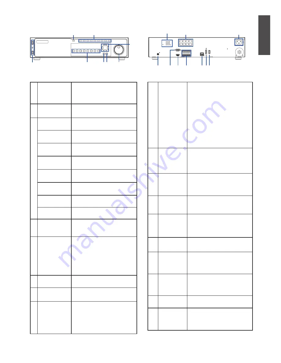
Table 2. Front Panel Descriptions
Table 3. Rear Panel Descriptions
Front panel I/O
Rear panel I/O
Figure 2. DNR-2060-08P Front Panel
Figure 3. DNR-2060-08P Rear Panel
1
4
7 8
6
5
3
2
1
4
7
8 9 10
6
5
3
2


