D-Link DGS-1510-28XMP Скачать руководство пользователя страница 4

  4

E

N

G

L

IS

H

Step 2

In order to login and configure the switch via an Ethernet 
connection, the PC must have an IP address in the same 
range as the switch. For example, if the switch has an 
IP address of 10.90.90.90, the PC should have an IP 
address of 10.x.y.z (where x/y is a number between 0 ~ 
254 and z is a number between 1 ~254), and a subnet 
mask of 255.0.0.0.

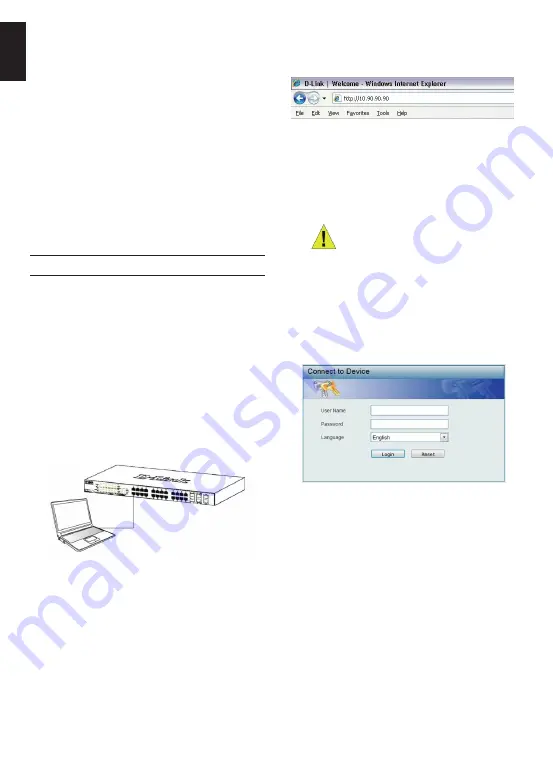
Open your web browser and enter http://10.90.90.90 
(the factory-default IP address) in the address box. Then 
press <Enter>.

Figure 8. Enter the IP address 10.90.90.90 in the web 

browser

The web configuration can also be accessed through the 
DNA. You can click the IP hyper link in the device list in 
the DNA to open the web GUI of devices.

NOTE: 

The switch’s factory default IP 

address is 10.90.90.90 with a subnet 
mask of 255.0.0.0 and a default 
gateway of 0.0.0.0

Power Failure

As a precaution, the switch should be unplugged in 
case of power failure. When power is resumed, plug the 
switch back in.

Management Options

Web-based Management Interface

After a successful physical installation, you can configure 
the switch, monitor the LED panel, and display statistics 
graphically using a web browser, such as Microsoft

®


Internet Explorer version 7.0 and higher, Firefox, Chrome 
or Safari.

You need the following equipment to begin the web 
configuration of your device:

•  A PC with a RJ-45 Ethernet connection

•  A standard Ethernet cable

Step 1

Connect the Ethernet cable to any of the ports in front 
panel of the switch and to the Ethernet port on the PC.

Figure 7. Connected Ethernet cable

This system may be managed out-of-band through the 
console port on the front/back panel or in-band using 
Telnet. The user may also choose the web-based 
management, accessible through a web browser. Each 
Switch must be assigned its own IP Address, which is 
used for communication with an SNMP network manager 
or other TCP/IP application (for example BOOTP, TFTP). 
The Switch’s default IP address is 10.90.90.90. The user 
can change the default Switch IP address to meet the 
specification of your networking address scheme.

Step 3

Figure 8. Enter Network Password window

Step 4

When the following logon dialog box appears, enter 
“admin” for both the Username and Password and 
choose the language of the Web-based Management 
interface then click Login.

Before entering the

 Web-based Management

, the 

Smart Wizard 

will guide you to quickly configure some 

functions, such as 

Ip Information, User Account and 

SNMP Settings

. If you don’t plan to change anything, 

click Exit to exit the Wizard and enter the Web-based 
Management. For a detailed look at the Smart Wizard’s 
functions, please refer to the Smart Wizard introduction 
in the user manual.

Содержание DGS-1510-28XMP

Страница 1: ...ый коммутатор SmartPro уровня 2 с 24 портами 10 100 1000Base T и 4 портами 10GBase X SFP 24 порта с поддержкой PoE 802 3af 802 3at 30 Вт PoE бюджет 370 Вт Getting Started Guide Layer 2 SmartPro Stackable Switch with 24 10 100 1000Base T PoE Ports and 4 10GBase X SFP Ports ...

Страница 2: ...e must be attached on the bottom at each corner of the device s base Allow enough ventilation space between the device and the objects around it Figure 1 Attaching the rubber feet Grounding the Switch depending on the purchased model This section describes how to connect the Switch to ground You must complete this procedure before powering on your Switch Required Tools and Equipment Grounding scre...

Страница 3: ... the AC power cord into the rear of the switch and to an electrical outlet preferably one that is grounded and surge protected Figure 6 Plugging the switch into an outlet Installing Power Cord Retainer To prevent accidental removal of the AC power cord it is recommended to install the power cord retainer together with the power cord 1 With the rough side facing down insert the Tie Wrap into the ho...

Страница 4: ...fari You need the following equipment to begin the web configuration of your device A PC with a RJ 45 Ethernet connection A standard Ethernet cable Step 1 Connect the Ethernet cable to any of the ports in front panel of the switch and to the Ethernet port on the PC Figure 7 Connected Ethernet cable This system may be managed out of band through the console port on the front back panel or in band u...

Страница 5: ...l connection on the management PC and configure the Properies of this connection a The Bits per second should be 115200 baud b The Data bits should be 8 c The Parity should be None d The Stop bits should be 1 e The Flow control should be None Figure 9 Hyperterminal Connection Properties 4 Now the Switch can be turned on and access to the Switch s CLI will be available Additional Information If you...

Страница 6: ...2013 E 2014 F 2015 G 2016 H 2017 I 2018 Месяц 1 январь 2 февраль 9 сентябрь A октябрь B ноябрь С декабрь 4 РУССКИЙ ПРАВИЛА И УСЛОВИЯ БЕЗОПАСНОЙ ЭКСПЛУАТАЦИИ 6 Внимательно прочитайте данный раздел перед установкой и подключением устройства Убедитесь что устройство и кабели не имеют механических повреждений Устройство должно быть использовано только по назначению в соответствии с кратким руководство...

Страница 7: ...чьте достаточное пространство для вентиляции между устройством и объектами вокруг него Рисунок 1 Крепление резиновых ножек Заземление коммутатора Данный раздел содержит информацию о способе заземления коммутатора Данную процедуру необходимо выполнить перед включением питания коммутатора Необходимые инструменты и оборудование Винт заземления M4 x 6 мм входит в комплект для монтажа Провод заземления...

Страница 8: ...ор может быть установлен в 19 дюймовую стойку EIA которая как правило размещается в серверной комнате вместе с другим оборудованием Прикрепите кронштейны к боковым панелям коммутатора и зафиксируйте их с помощью входящих в комплект поставки винтов Рисунок 4 Крепление кронштейнов Установите коммутатор в стойку и закрепите его с помощью винтов входящих в комплект поставки стойки Рисунок 5 Установка ...

Страница 9: ...мутатора по умолчанию для соответствия схеме адресации сети Управление на основе Web интерфейса После успешной установки можно выполнить настройку коммутатора следить за его состоянием с помощью графически статистику в Web браузере например в Microsoft Internet Explorer версии 7 0 и выше Firefox Для настройки устройства через Web интерфейс потребуется следующее оборудование Компьютер с интерфейсом...

Страница 10: ...и о DNA обратитесь к руководству пользователя Вариант 2 Выполните следующие шаги чтобы установить DNA вручную 1 Вставьте компакт диск входящий в комплект поставки в привод CD ROM 2 В меню Пуск на рабочем столе Windows выберите Мой компьютер 3 Дважды нажмите на значке привода CD ROM чтобы открыть меню автозапуска или нажмите правой кнопкой мыши на значке привода чтобы открыть папку Выберите DNA D L...

Страница 11: ... вентилятора Вес 4 25 кг Влажность при хранении От 0 до 95 без конденсата Технические характеристики Производительность Коммутационная матрица 128 Гбит с Метод коммутации Store and forward Макс скорость перенаправления 64 байтных пакетов 95 24 Mpps Размер таблицы MAC адресов 16K записей Объем оперативной памяти 256 МБ DDR3 Буфер пакетов 1 5 МБ Флэш память 32 МБ Максимальная 436 3 функция PoE включ...

Страница 12: ...495 744 00 99 E mail mail dlink ru Україна Київ вул Межигірська 87 А Тел 38 044 545 64 40 E mail ua dlink ua Moldova Chisinau str C Negruzzi 8 Tel 373 22 80 81 07 E mail info dlink md Беларусь Мінск пр т Незалежнасці 169 Тэл 375 17 218 13 65 E mail support dlink by Қазақстан Алматы Құрманғазы к cі 143 үй Тел 7 727 378 55 90 E mail almaty dlink ru Հայաստան Երևան Դավթաշեն 3 րդ թաղամաս 23 5 Հեռ 374 1...

Отзывы: