DGS-1510/ME Series Metro Ethernet Switch Hardware Installation Guide
25
inadvertent failure of the internal power-supply of an Ethernet switch, which can result in the shutdown of that switch,
the devices attached to its ports, or an entire network.
CAUTION:
Do not connect the RPS to AC power before the DC power cable is connected. This
might damage the internal power supply.
Connecting the RPS to the RPS Port
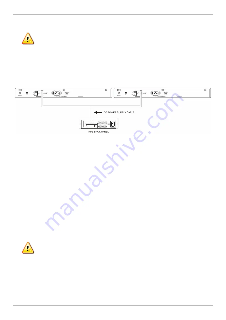
The D-Link RPS can be connected to the RPS port of the Switch using the DC power supply cord, called the DPS-
CB150-2PS (HW: B1). It is important to notice that the RPS can supply power to one or two DGS-1510/ME Switches
at the same time.
Figure 2-11 Connecting two Switches to the RPS
The following section explains how to connect the RPS to the Switch.
1. Disconnect the Switch from the main AC power source.
2. Insert the 14-pin end of the DC power supply cord into the RPS and the 2-pin end into the receptacle of the
RPS port on the Switch.
3. Using a standard AC power cord, connect the RPS to the main AC power source. A green LED on the front
panel of the RPS will illuminate to indicate a successful connection.
4. Make sure that the ON/OFF toggle switch on the rear panel of the Switch is turned on.
5. Re-connect the Switch to the AC power source and power on the RPS.
No configuration is needed in the Switch software for this installation.
Installing the RPS into a Rack-mount Chassis
The D-Link RPS can be installed into D-Link RPS rack-mount chassis unit.
CAUTION:
Do not connect the RPS to the AC power before the DC power cable is connected.
Connecting the AC power before the DC power is connected might damage the internal power
supply.
Содержание DGS-1510-10L/ME
Страница 1: ......
Страница 3: ... FCC 21 CFR Chapter 1 Subchapter J in accordance with FDA CDRH requirements ...
Страница 67: ......


