background image

  2

E

N

G

LIS

H

About This Guide

This guide gives step-by-step instructions for setting up  

all D-Link Metro Ethernet switches and relative Warranty, 

Safety, Regulatory, and Environment Notice. Please note 

that the model you have purchased may appear slightly 

different from those shown in the illustrations.
For more detailed information about your switch, its 

components, making network connections, and technical 

specifications, please refer to the User’s Guide. 

Step 1 – Unpacking

Open the shipping carton and carefully unpack its 

contents. Please consult the packing list located in the 

User Guide to make sure all items are present and 

undamaged. If any item is missing or damaged, please 

contact your local D-Link reseller for replacement.

Step 2 – Switch Installation

For safe switch installation and operation, it is 

recommended that you:

• Visually inspect the power cord to see that it is secured 

fully to the AC power connector.

• Make sure that there is proper heat dissipation and 

adequate ventilation around the switch.

• Do not place heavy objects on the switch

Desktop or Shelf Installation

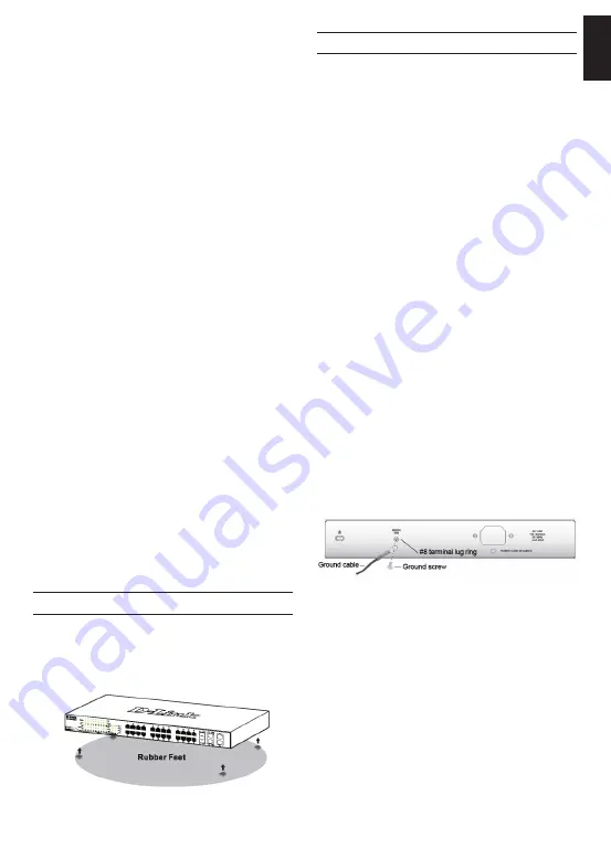
When installing the switch on a desktop or shelf, the 

rubber feet included with the device must be attached 

on the bottom at each corner of the device’s base. Allow 

enough ventilation space between the device and the 

objects around it.

Figure 1. Attaching the rubber feet

Grounding the Switch  

This section describes how to connect the Switch to 

ground. You must complete this procedure before 

powering on your Switch. 

Required Tools and Equipment

•  Grounding screws (included in the accessory kit): 

One M4 x 6 mm (metric) pan-head screw

•  Grounding cable (not included in the accessory kit): 

The grounding cable should be sized according 

to local and national installation requirements. 

Depending on the power supply and system, a 

12 to 6 AWG copper conductor is required for 

installation. Commercially available 6 AWG wire is 

recommended. The length of the cable depends 

on the proximity of the Switch to proper grounding 

facilities.

• 

A screwdriver (not included in the accessory kit)

You can connect the Switch to a protective ground by 

following the steps below:
1.  Verify if the system power is off.
2. 

Use the grounding cable to place the #8 terminal 

lug ring on top of the ground-screw opening.

3.  Insert the grounding screw into the ground-screw 

opening. 

4. 

Using a screwdriver, tighten the grounding screw to 

secure the grounding cable to the Switch.

5. 

Attach the terminal lug ring at the other end of the 

grounding cable to an appropriate grounding stud or 

bolt on rack where the Switch is installed.

6.  Verify if the connections at the ground connector on 

the Switch and the rack are securely attached.

Figure 2. Connect a Grounding Cable

- DGS-1210-28X/ME D-Link Switch 

- Rack mounting bracket
- Power cord

- One console cable

- Power cord retainer

-  User’s Guide CD with DNA (D-Link Network Assistant) 

program (optionally)

- One Getting Started Guide

- An accessory kit for one ground screw
 
  Is not supplied with DGS-1210-28X/ME/B1B.                                                                                                                                             

*

*

*

*

*

Содержание DGS-1210-28X/ME

Страница 1: ... on D Link Website Getting Started Guide Краткое руководство по установке DGS 1210 28Х ME 24 10 100 1000Base T 4 10G SFP Ports L2 Management Switch Управляемый L2 коммутатор с 24 портами 10 100 1000Base T и 4 портами 10GBase X SFP ...

Страница 2: ...scribes how to connect the Switch to ground You must complete this procedure before powering on your Switch Required Tools and Equipment Grounding screws included in the accessory kit One M4 x 6 mm metric pan head screw Grounding cable not included in the accessory kit The grounding cable should be sized according to local and national installation requirements Depending on the power supply and sy...

Страница 3: ...an SNMP network manager or other TCP IP application for example BOOTP TFTP The Switch s default IP address is 10 90 90 90 The user can change the default Switch IP address to meet the specification of your networking address scheme Web based Management Interface After a successful physical installation you can configure the switch monitor the LED panel and display statistics graphically using a we...

Страница 4: ... on your CD Rom DVD Rom Drive to start the autorun menu or right click on the Drive to open the folder Select DNA D Link Network Assistant and double click on the setup exe file 4 Follow the on screen instructions to install the utility 5 Upon completion go to Start Programs D Link DNA and open the DNA D Link Network Assistant 6 Just connect the Smart Switch to the same L2 network segment of your ...

Страница 5: ...nction is default Disabled for D Link managed switches D View SNMP Network Management System is a comprehensive standard based management tool designed to centrally manage critical network D View provides useful tools to allow network administrators to effectively manage device configurations fault tolerance performance and security D Link offers free D View trial version download that allows you ...

Страница 6: ...питания указанным в технических характеристиках устройства Не вскрывайте корпус устройства Перед очисткой устройства от загрязнений и пыли отключите питание устройства Удаляйте пыль с помощью влажной салфетки Не используйте жидкие аэрозольные очистители или магнитные статические устройства для очистки Избегайте попадания влаги в устройство Устройство должно также быть заземлено если это предусмотр...

Страница 7: ...ые или нагревающиеся объекты на коммутаторе Установка на стол или поверхность При установке коммутатора на стол или какую нибудь поверхность необходимо прикрепить к нему поставляемые вместе с ним резиновые ножки Самоклеющиеся ножки крепятся на дне устройства по его углам Обеспечьте достаточное пространство для вентиляции между устройством и объектами вокруг него Рисунок 1 Крепление резиновых ножек...

Страница 8: ...панели коммутатора и к порту Ethernet на компьютере Рисунок 7 Подключение Ethernet кабеля 8 РУССКИЙ Системой можно управлять локально через консольный порт на передней панели либо удаленно используя Telnet Пользователь также может управлять коммутатором через Web интерфейс посредством Web браузера Каждому коммутатору должен быть назначен IP адрес который используется для взаимодействия с сетевым м...

Страница 9: ...рограммы автозапуска появится автоматически 3 Просто нажмите на кнопке Install DNA D Link Network Assistant и выполните установку с помощью Мастера 4 После успешного завершения установки DNA можно будет найти в Start Programs D Link DNA Пуск Программы D Link DNA 5 Просто подключите коммутатор серии Smart к тому же L2 сегменту сети в котором находится компьютер и воспользуйтесь DNA D Link Network A...

Страница 10: ... зависимости от настроенного IP адреса и нажмите кнопку Enter на клавиатуре Перейдите в окно консоли для управления коммутатором с помощью интерфейса командной строки введите admin в качестве имени пользователя по умолчанию и пароль а затем нажмите кнопку Enter Управление с помощью SNMP Можно управлять коммутатором с помощью утилиты D Link D View или любой консольной программой совместимой с SNMP ...

Страница 11: ...T Gigabit Ethernet медная витая пара Полный дуплекс для скорости 1000 Мбит с Производительность Коммутационная матрица 128 Гбит с Макс скорость перенаправления 64 интерфейс настройте с помощью байтных Размер таблицы MAC адресов 16K записей Макс потребляемая мощность Система вентиляции 1 вентилятор Smart Link Activity Speed на порт RPS Fan Error пакетов 95 24 Mpps Буфер пакетов 1 5 МБ Метод коммута...

Страница 12: ...12 РУССКИЙ ...

Отзывы: