D-Link DGS-1210-10P Скачать руководство пользователя страница 40

5  Configuration


D-Link Web Smart Switch User Manual


3

3

5

5


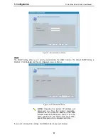
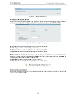
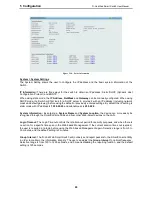
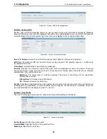
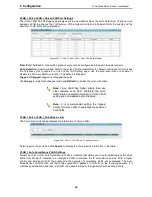
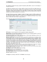
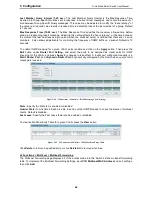
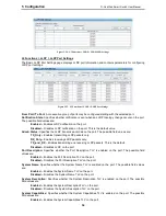
IEEE802.3az EEE compliance. By default, the switch enabled the 802.3az EEE function. Users can disable 
this feature by individual port via the IEEE802.3az EEE setting page. 


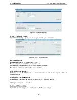
Figure 5.29 – System > IEEE802.3az EEE Settings 


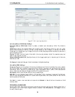
From Port / To Port:

 A consecutive group of ports may be configured starting with the selected port. 

State:

 Enabled or Disabled the IEEE802.3az EEE for the specified ports. By default, all ports are enabled. 

Click 

Apply

 to implement changes made. 


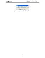
If the connection speed drops down from 1000M to 100M, or the first link up takes longer time, please follow 
below steps and check again: 

1. 

Upgrade drivers of your Ethernet adapter or LAN controller for the host PC.  

2. 

Disable EEE function on the switch port. 
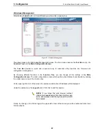
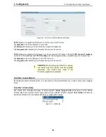
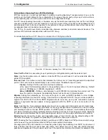
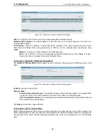
 

VLAN > 802.1Q VLAN 

A VLAN is a group of ports that can be anywhere in the network, but communicate as though they were in 
the same area. 

VLANs can be easily organized to reflect department groups (such as R&D, Marketing), usage groups (such 
as e-mail), or multicast groups (multimedia applications such as video conferencing), and therefore help to 
simplify network management by allowing users to move devices to a new VLAN without having to change 
any physical connections. 

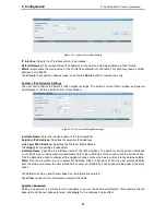
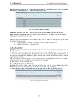
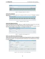
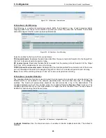
The IEEE 802.1Q VLAN Configuration page provides powerful VID management functions.  The original 
settings have the VID as 1, no default name, and all ports as “Untagged” 
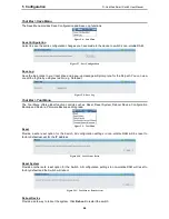
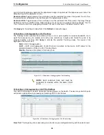
Rename:

 Click to rename the VLAN group. 

Delete VID:

 Click to delete the VLAN group. 
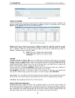
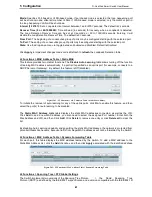
Add  New VID:

  Click  to create a  new VID group, assigning  ports  from  01  to  28  as 

Untag

Tag

,  or 

Not 

Member

. A port can be untagged in only one VID. To save the VID group, click

 Apply. 

You may change the name accordingly to the desired groups, such as R&D, Marketing, email, etc.  


Figure 5.30 – Configuration > 802.1Q VLAN  


Содержание DGS-1210-10P

Страница 1: ......

Страница 2: ...Installation 7 Step 1 Unpacking 7 Step 2 Switch Installation 7 Desktop or Shelf Installation 7 Rack Installation 7 Step 3 Plugging in the AC Power Cord 8 Power Failure 9 3 Getting Started 10 Manageme...

Страница 3: ...System Power Saving 34 System IEEE802 3az EEE Settings 34 VLAN 802 1Q VLAN 35 VLAN 802 1Q VLAN PVID 36 VLAN 802 1Q Management VLAN 36 VLAN Voice VLAN Voice VLAN Global Settings 36 VLAN Voice VLAN Voi...

Страница 4: ...y Safeguard Engine 60 Security Storm Control 60 Security ARP Spoofing Prevention 60 Security DHCP Server Screening 61 Security SSL Settings 61 Security Smart Binding Smart Binding Settings 62 Security...

Страница 5: ...ig account admin password 96 save 97 debug info 97 Appendix A Ethernet Technology 99 Gigabit Ethernet Technology 99 Fast Ethernet Technology 99 Switching Technology 99 Appendix B Technical Specificati...

Страница 6: ...s Terms Usage In this guide the term Switch first letter capitalized refers to the Smart Switch and switch first letter lower case refers to other Ethernet switches Some technologies refer to terms sw...

Страница 7: ...upport 802 1p priority queues enabling users to run bandwidth sensitive applications such as streaming multimedia by prioritizing that traffic in network These functions allow switches to work seamles...

Страница 8: ...seconds the Switch will change back to the default configuration and all changes will be lost Mode By pressing the Mode button the Port LED will switch between Link Act and PoE modes Port Link Act Sp...

Страница 9: ...fault configuration and all changes will be lost Rear Panel Figure 1 4 DGS 1210 20 Rear Panel Power The power port is where to connect the AC power cord DGS 1210 28 24 Port 10 100 1000Mbps plus 4 SFP...

Страница 10: ...n mode LED lights up in Link Act mode the port LEDs indicate a network link through the corresponding port Blinking indicates the Switch is either sending or receiving data to the port When the port L...

Страница 11: ...ng or receiving data to the port When a port has an amber light this indicates that the port is running on 10M or 100M When it has a green light it is running on 1000M Fan The Fan LED lights green whe...

Страница 12: ...tch installation and operation it is recommended that you Visually inspect the power cord to see that it is secured fully to the AC power connector Make sure that there is proper heat dissipation and...

Страница 13: ...quipment is not compromised C Mechanical Loading Mounting of the equipment in the rack should be such that a hazardous condition is not achieved due to uneven mechanical loading D Circuit Overloading...

Страница 14: ...2 Hardware Installation D Link Web Smart Switch User Manual 9 9 Power Failure As a precaution the switch should be unplugged in case of power failure When power is resumed plug the switch back in...

Страница 15: ...d to change the IP address of your PC and it is easier to initialize multiple Smart Switches Please refer to the following installation instructions for the Web based Management and the SmartConsole U...

Страница 16: ...ly load the web configuration in your web browser When the following logon dialog box appears enter the password and choose the language of the Web based Management interface then click OK The switch...

Страница 17: ...ion 2 Follow these steps to install the SmartConsole Utility manually 1 Insert the Utility CD into your CD Rom DVD Rom Drive 2 From the Start menu on the Windows desktop click Computer 3 In the Run di...

Страница 18: ...Monitor list and About Utility Settings Click this icon to launch the Utility Settings window Refresh time refreshes the devices which were selected as monitored devices in the Device List Choices in...

Страница 19: ...on to launch the Trap window Click View Trap to show the events of the SmartConsole Utility and the device Time indicates when the trap message was received Location indicates the physical location of...

Страница 20: ...e SmartConsole Info window Figure 4 6 SmartConsole About Device Configuration The Device Configuration in the SmartConsole Utility has five icons Device Settings Password Setting Firmware Upgrade DHCP...

Страница 21: ...d confirm it Figure 4 8 SmartConsole Password Setting Firmware Upgrade Select one or many switches of the same model name from the Device List Click on this icon to launch the Firmware Upgrade window...

Страница 22: ...r the correct Device Password and then click OK The device will renew the IP address from the DHCP server Figure 4 10 DHCP Refresh Web Access Select a switch from the Device List Click this icon to la...

Страница 23: ...on will change to Please check if the power or the cable of this device is disconnected Product Name Displays the device product name IP Address Displays the current IP addresses of devices Subnet Mas...

Страница 24: ...t Switch User Manual 1 19 9 again NOTE If the IP address of device is showed with IPv6 address then it can not be configured with Smartconsole Utility The user needs to double click the selected devic...

Страница 25: ...IP Information access password and SNMP Select Static DHCP or BOOTP and enter the desired new IP Address select the Netmask and enter the Gateway address then click the Next button to enter the next...

Страница 26: ...nabled and then click Apply to make it effective Figure 5 3 SNMP in Smart Wizard NOTE Changing the system IP address will disconnect you from the current connection Please enter the correct IP address...

Страница 27: ...5 Configuration D Link Web Smart Switch User Manual 22 Figure 5 4 Confirm the changes of IP address in Smart Wizard...

Страница 28: ...t functions in the Function Tree you can change all the settings in the Main Configuration Screen The main configuration screen will show the current status of your Switch by clicking the model name o...

Страница 29: ...ad Figure 5 8 Save Log Tool Bar Tool Menu The Tool Menu offers global function controls such as Reset Reset System Reboot Device Configuration Backup and Restore Firmware Backup and Upgrade Figure 5 9...

Страница 30: ...r a saved backup settings file Click Restore after selecting the backup settings file you want to restore TFTP TFTP Trivial File Transfer Protocol is a file transfer protocol that allows you to transf...

Страница 31: ...to restore from Click Backup to save the firmware to the TFTP server Click Upgrade after selecting the firmware file you want to restore CAUTION Do not disconnect the PC or remove the power cord from...

Страница 32: ...5 Configuration D Link Web Smart Switch User Manual 2 27 7 Figure 5 16 User Guide Micro Site...

Страница 33: ...e STP Global Settings Default is disabled Port Mirroring Click Settings to link to L2 Functions Port Mirroring Default is disabled Storm Control Click Settings to link to Security Storm Control Defaul...

Страница 34: ...d subnet mask is 255 0 0 0 System Information By entering a System Name and System Location the device can more easily be recognized through the SmartConsole Utility and from other Web Smart devices o...

Страница 35: ...led or disabled DHCPv6 Client Specifies the DHCPv6 client to be enabled or disabled IPv6 Network Address Specifies the IPv6 Network Address NS Retransmit Time Settings NS Retransmit Time 1 3600 Specif...

Страница 36: ...neighbor IPv6 address Link Layer MAC Address Specifies the link layer MAC address Click Apply for the settings to take effect Interface Name Specifies the interface name of the IPv6 neighbor To search...

Страница 37: ...have to use straight through Ethernet cables to make sure the Tx Rx pairs match up properly When connecting the Switch to other networking devices a crossover cable must be used This switch provides...

Страница 38: ...minimum severity from which warning messages are sent to the server There are three levels When a severity level is selected all severity level choices above the selection are selected automatically...

Страница 39: ...ate is disabled On the contrary if the LED is enabled the Time Profile function will work Port Shut off The Port Shut off state has high priority the priority rule is the same as LED Therefore if the...

Страница 40: ...N is a group of ports that can be anywhere in the network but communicate as though they were in the same area VLANs can be easily organized to reflect department groups such as R D Marketing usage gr...

Страница 41: ...k more flexible By default the Management VLAN is disabled You can select any existing VLAN as the management VLAN when this function is enabled There can only be one management VLAN at a time Figure...

Страница 42: ...onally Unique Identifier OUI is the first three bytes of the MAC address This identifier uniquely identifies a vendor manufacturer or other organization There are some pre defined OUIs and when the us...

Страница 43: ...table Note Voice VLAN has higher priority than any other features even QoS Therefore the voice traffic will be operated according to Voice VLAN setting and not impacted by QoS feature Note It is reco...

Страница 44: ...global settings User defined MAC Settings Component Type Auto Surveillance VLAN will automatically detect D Link Surveillance Devices by default There are another five surveillance components that cou...

Страница 45: ...and receive mode Duplicate both the data transmitted from and data sent to the source port and forwards all the data to the assigned Target Port Click all to include all ports into port mirroring None...

Страница 46: ...rt isn t specified as an uplink port for example connects to a DHCP Server or Gateway By default this feature is Off disabled Figure 5 41 L2 Functions MAC Address Table Static Mac Address To initiate...

Страница 47: ...unt 1 10 Used to set the maximum number of Hello packets transmitted per interval The count can be specified from 1 to 10 The default is 6 Maximum Age 6 40 sec This value may be set to ensure that old...

Страница 48: ...100Mbps port 200000 Gigabit port 20000 Value 1 200000000 Define a value between 1 and 200000000 to determine the external cost The lower the number the greater the probability the port will be chosen...

Страница 49: ...he combining of two or more ports together to increase bandwidth Up to eight Trunk groups may be created and each group consists up to eight ports Select the ports to be grouped together and then clic...

Страница 50: ...rs attached The settings of IGMP snooping is set by each VLAN individually Figure 5 47 L2 Functions Multicast IGMP Snooping By default IGMP is disabled If enabled the IGMP Global Settings will need to...

Страница 51: ...he Apply button Then press the Edit button under Router Port Setting and select the ports to be assigned as router ports for IGMP snooping for the VLAN and press Apply for changes to take effect A rou...

Страница 52: ...st Multicast Filtering Mode The Multicast Filtering Mode function allows users to select the filtering mode for IGMP group per VLAN basis Figure 5 50 L2 Functions Multicast Multicast Filtering Mode VL...

Страница 53: ...ndary SNTP server from which the system time is retrieved SNTP Poll Interval in Seconds 30 99999 Defines the interval in seconds at which the SNTP server is polled for Unicast information The Poll Int...

Страница 54: ...ets the switch will learn the information from the LLDP packets advertised from the neighbor in the neighbor table Click Apply to make the change effective Message TX Hold Multiplier 2 10 This paramet...

Страница 55: ...ckets only RX_Only Enables receiving LLDP packets only TX_and_RX Enables transmitting and receiving LLDP packets This is the default Disabled Disables LLDP on the port Port Description Specifies wheth...

Страница 56: ...f VLAN ID or VLAN Name or all Protocol Identity Specifies the Protocol Identity to be enabled or disabled in the LLDP port If select Enabled users can specifies the EAPOL LACP GVRP STP or ALL Click Ap...

Страница 57: ...Apply to implement changes made and click Refresh to refresh the table information L2 Functions LLDP LLDP Management Address Settings The LLDP Management Address Settings allows the user to set manag...

Страница 58: ...the SNMP OID Advertising Ports Displays the advertising ports L2 Functions LLDP LLDP Local Port Table The LLDP Local Port Table page displays LLDP local port information Figure 5 60 L2 Functions LLDP...

Страница 59: ...s LLDP LLDP Remote Port Table This LLDP Remote Port Table page is used to display the LLDP Remote Port Brief Table Select port number and click Search to display additional information Figure 5 63 L2...

Страница 60: ...LLDP Remote Port Normal Table To view the detail settings for a remote port click View Detailed and the following page displays Figure 5 65 L2 Functions LLDP LLDP Remote Port Detailed Table L2 Functio...

Страница 61: ...s the total number of LLDP frames transmitted on the port RxPort FramesDiscarded Displays the total discarded frame number of LLDP frames received on the port RxPort FramesErrors Displays the Error fr...

Страница 62: ...QoS is an implementation of the IEEE 802 1p standard that allows network administrators to reserve bandwidth for important functions that require a larger bandwidth or that might have a higher priori...

Страница 63: ...to the port The priorities are Highest High Medium and Low Click Apply for the settings to take effect QoS TCP UDP Port Priority Settings The TCP UDP Port Priority Settings page allows user to config...

Страница 64: ...anted address and then click Apply Security Port Security Port Security is a security feature that prevents unauthorized computers with source MAC addresses unknown to the Switch prior to stopping aut...

Страница 65: ...ticast Broadcast Unknown Unicast Threshold 64Kbps N If storm control is enabled default is disabled the threshold is from of 64 1 024 000 Kbit per second with steps N of 64Kbps N can be from 1 to 1600...

Страница 66: ...5 77 Security DHCP Server Screening Trusted DHCP Server IP Settings Select IPv4 or IPv6 and specify the IP address then click Apply to create Trusted DHCP Server Click Add to add a DHCP trusted DHCP...

Страница 67: ...witch Figure 5 79 Security Smart Binding Smart Binding Settings The Smart Binding Settings page contains the following fields From Port To Port Select a range of ports to set for IP MAC port binding S...

Страница 68: ...the MAC address set below MAC Address Specifies the MAC address to bind to the IP address set above Port Specify the switch ports for which to configure this IP MAC binding entry IP Address MAC Addres...

Страница 69: ...lect all entries or click Clean to select none of the entries AAA 802 1X 802 1X Settings Network switches provide easy and open access to resources by simply attaching a client PC Unfortunately this a...

Страница 70: ...he exchanges between the Authenticator and the client Default is 30 seconds ServerTimeout 1 65535 sec Sets the amount of time the switch waits for a response from the client before resending the respo...

Страница 71: ...on will be on packets from this IPv4 source address IPv6 Address Indicates ACL action will be on packets from this IPv6 source address To Specify the destination of accessible packets The possible val...

Страница 72: ...tch the ACL criteria Figure 5 85 ACL ACL Profile List The contents of Access Profile List table include Profile ID Indicates the profile Identification number The possible configured profile IDs are 1...

Страница 73: ...Type MAC IPv4 or IPv6 specify attributes like Untagged Tagged for MAC ICMP IGMP TCP UDP for IPv4 or ICMP TCP UDP for IPv6 Click Select and a simplified frame diagram will be displayed Figure 5 87 Add...

Страница 74: ...h 802 1Q fields in the Layer 2 header Untagged Defines the profile Layer 2 to check the Layer 2 header without the 802 1Q fields IPv4 ACL Defines the IPv4 ACL profile protocols The possible fields are...

Страница 75: ...instructs the Switch to examine the 802 1Q VLAN identifier of each packet header and use this as the full or partial criterion for forwarding VLAN ID Selecting this option instructs the Switch to exam...

Страница 76: ...ple to set 176 212 XX XX use mask 255 255 0 0 Destination IP Mask Defines the range of destination IP addresses relevant to the ACL rules 0 ignore 1 check For example to set 176 212 XX XX use mask 255...

Страница 77: ...2 Figure 5 90 Add Access Profile IPv4 ACL IGMP Click Add button then the ACL profile is added To define the IPv4 ACL TCP profile Select IPv4 ACL with TCP and click Select button The updates to show th...

Страница 78: ...he ACL profile is added To define the IPv4 ACL UDP profile Select IPv4 ACL with UDP and click Select button The updates to show the follows Figure 5 92 Add Access Profile IPv4 ACL UDP The Add ACL Prof...

Страница 79: ...resses relevant to the ACL rules 0 ignore 1 check For example to set 2002 0 0 0 0 0 b0d4 0 use mask 128 Destination IP Prefix Defines the range of destination IP addresses relevant to the ACL rules 0...

Страница 80: ...range of source Ports relevant to the ACL rules 0 ignore 1 check For example to set 0 15 set mask of FFF0 Destination Port Mask Defines the range of destination IP addresses relevant to the ACL rules...

Страница 81: ...For example to set 0 15 set mask of F Click Add button then the ACL profile is added NOTE A combination of one or several filtering masks can be selected simultaneously The page updates with the rele...

Страница 82: ...rofile ID and Ether Type In Rule Detail you can specify the details of an access rule Below are all the possible parameters that can be set Access ID Specify the Access ID 1 65535 Type Display the typ...

Страница 83: ...the corresponding Delete button Figure 5 100 ACL ACL Finder PoE PoE Global Settings DGS 1210 10P 28P only This page will display the PoE status including System Budget Power Support Total Power Remain...

Страница 84: ...n 802 3af capable D Link AP IP Cam and IP phone equipment via the PoE splitter DWL P50 IEEE 802 3at defined that the PSE provides power according to the following classification Class Usage Output pow...

Страница 85: ...PD SNMP Trap to SmartConsole Utility By configuring the Trap Setting it allows SmartConsole Utility to monitor specified events on this Web Smart Switch By default Trap Setting is disabled When the Tr...

Страница 86: ...ion over the network The default SNMP global state is disabled Select Enable and click Apply to enable the SNMP function Figure 5 104 SNMP SNMP SNMP Global Settings Trap Settings Specifies whether the...

Страница 87: ...ntrol MIB access policy security policy for a user group directly Group Name Specify the SNMP user group of up to 32 characters Read View Name Specify a SNMP group name for users that are allowed SNMP...

Страница 88: ...bject number is concerned 0 means do not concerned For example 1 3 6 1 2 1 1 with mask 1 1 1 1 1 1 0 means 1 3 6 1 2 1 X View Type Specify the configured OID is Included or Excluded that a SNMP manage...

Страница 89: ...fier used to identify the SNMPv3 engine on the Switch Input the Engine ID then click Apply to apply the changes and click Default resets to default value Figure 5 110 SNMP SNMP SNMP Engine ID SNMP RMO...

Страница 90: ...the number of buckets that the device saves Interval 1 3600 Indicates in seconds the time period that samplings are taken from the ports The field range is 1 3600 The default is 1800 seconds equal to...

Страница 91: ...s take effects SNMP RMON RMON Event The RMON Event page contains fields for defining modifying and viewing RMON events statistics Figure 5 115 SNMP RMON RMON Event Settings The RMON Events Page contai...

Страница 92: ...ermines the type of cable errors occurred in the cable Select a port and then click the Test Now button to start the diagnosis Figure 5 118 Monitoring Cable Diagnostic Test Result The description of t...

Страница 93: ...ion when the device was booted how the ports are operating when users logged in when sessions timed out as well as other system information Figure 5 119 Monitoring System Log ID Displays an incremente...

Страница 94: ...e case sensitive Press Enter in both the Username and Password fields The command prompt will appear as shown below DGS 1210 52 DGS 1210 52 login admin Password DGS 1210 52 Figure 6 1 Command Prompt T...

Страница 95: ...way gw address dhcp debug info download firmware_fromTFTP tftp ip address filename cfg_fromTFTP tftp ip address filename logout ping ip_addr reboot reset config save show ipif show switch upload firmw...

Страница 96: ...10 52 download firmware_fromTFTP 1 1 1 23 1 dgs _1210 10032 ros 01 J an 2000 01 19 48 COPY I FIL E CPY Files Copy s ource UR L tftp 1 1 1 23 1 dgs _1210 10032 ros des tination UR L Unit all flas h ima...

Страница 97: ...1 J an 2000 01 26 16 COPY W TR AP The copy operation was completed s ucces s fully 158 bytes copied in 00 00 05 hh mm s s DGS 1210 52 config ipif system Purpose To configure the System IP interface Sy...

Страница 98: ...single IP interface Ex 3ffe 501 ffff 100 1 64 The 64 represents the prefix length of the IPv6 addresses dhcpv6_client enable disable Specify the DHCPv6 client to be disabled or enabled Restrictions No...

Страница 99: ...secs 10 90 90 91 Ping Statistics 3 Packets Transmitted 3 Packets Received 0 Packets Loss DGS 1210 52 ping6 Purpose To test the connectivity between network devices Syntax ping6 ipv6addr Description Th...

Страница 100: ...es to re login DGS 1210 52 reset config Purpose To reset the Switch to the factory default settings Syntax res et config Description All configurations will be reset to the default settings Parameters...

Страница 101: ...itch information DGS 1210 52 show switch System Name System Contact System Location System up time 0 days 6 hrs 32 min 17 secs System Time 02 01 2012 06 32 19 System hardware version B1 System firmwar...

Страница 102: ...sage To save the Switch s current configuration to non volatile RAM DGS 1210 52 save Building configuration OK DGS 1210 52 debug info Purpose To display the ARP table and MAC FDB information of the Sw...

Страница 103: ...rt Switch User Manual 98 10 90 90 98 00 19 5b 14 3d c4 ARPA vlan1 Dynamic 10 255 255 255 ff ff ff ff ff ff ARPA vlan1 Static MAC table Vlan Mac Address Type Ports 1 00 00 00 00 00 26 Learnt Gi0 7 Tota...

Страница 104: ...r unshielded twisted pair UTP cabling a flexible foundation for the next generation of network technology products will be created This will outfit your network with a powerful 1000 Mbps capable backb...

Страница 105: ...Ethernet on Port 1 Port 8 GE ports DGS 1210 10P IEEE802 3at Power over Ethernet on Port 1 Port 4 GE ports DGS 1210 28P only SFP ports compliant with the following standards IEEE 802 3z Supports Full D...

Страница 106: ...ffic Segmentation D Link Safeguard Engine Broadcast Storm Control ARP Spoofing Prevention Supports max 64 entries DHCP Server Screening Able to configure 5 IP addresses for DHCP server SSL Support v1...

Страница 107: ...Port Standby Each port on the system enters sleep state by schedule By System Hibernation System enters hibernation by schedule In this mode switches save most power since main chipsets both MAC and...

Страница 108: ...ion of the equipment in a rack should be such that the amount of air flow required for safe operation of the equipment is not compromised C Mechanical Loading Mounting of the equipment in the rack sho...

Страница 109: ......

Отзывы: