background image

D-Link Switch User Manual


Powering on the Switch 

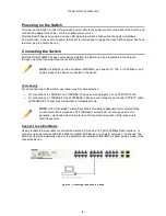
To power on the Switch, connect the provided power cable to the power socket on the back of the Switch, and 

connect the adapter side of the cord to a suitable power source.   
After the Switch has been powered on, the LED indicators will blink briefly while the system initializes.  
As a precaution, in the event of a power failure it is recommended to unplug the Switch. When power has been 

restored, plug the Switch back in. 
 

Connecting the Switch 

After the DGS-1026MP has been successfully installed, the Switch can be integrated into the network 

through one of the following three connection methods:  


Cable Quality 

For all connections to the Switch, use these rules for cable selection: 


  For connections to 10BASE-T and 100BASE-TX devices, use Category 5 or 5e UTP/STP cable. 

  For connections to 100BASE-TX and 1000BASE-T devices, use Category 5e or better UTP/STP cable. 

All 1000BASE-T connections will operate in full-duplex mode. 


Connect to an End Node 

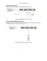
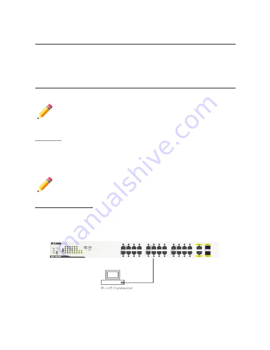
Use a standard Ethernet cable to connect the Switch to PCs with a 10/100/1000 Mbps RJ45 interface, or 

connect and power remote IEEE 802.3af/at-compliant PoE devices, such as IP cameras or IP phones. The 

Switch ports will automatically adjust to the hardware characteristics (MDI/MDIX, speed, duplex mode) of the 

connected device. 


Figure 8 – Connecting the Switch to a node 


NOTE:

 All Ethernet ports auto-detect MDI/MDIX, port speed (10, 100, or 1000 Mbps), and 

duplex mode of the device connected to the Switch. 


NOTE:

 UTP (Unshielded Twisted Pair) Ethernet cabling is adequate for most small office 

environments. More expensive STP (Shielded Twisted Pair) can also be used, but is 

generally only needed when there is risk of strong electromagnetic interference due to 

radio frequencies. 

Содержание DGS-1026MP

Страница 1: ......

Страница 2: ... the Switch in a Rack 5 Powering on the Switch 6 Connecting the Switch 6 Connect to an End Node 6 Connect to a Hub or Switch 7 Connect to a Network Backbone or Server 7 Understanding the Switch s Features 8 Power Over Ethernet PoE 8 Power Saving 8 Appendix A Technical Specifications 9 Hardware Specifications 9 Key Components Performance 9 Ports 9 Port Standards 9 Physical Environment 9 Emission EM...

Страница 3: ...tion to use the device properly A CAUTION indicates potential property damage or personal injury Copyright and Trademarks Information in this document is subjected to change without notice 2016 D Link Corporation All rights reserved Reproduction in any manner whatsoever without the written permission of D Link Corporation is strictly forbidden Trademarks used in this text D Link and the D LINK log...

Страница 4: ... Guide If any item is found missing or damaged please contact your local retailer for replacement Product Overview Front Panel Figure 1 DGS 1026MP Front Panel Item Description LED MODE Press to change the port LEDs to display the PoE status or the link status The color of the LED Mode light will indicate which LED status display is currently active Green LEDs means the Switch is currently showing ...

Страница 5: ...on is between 101 and 200 W Solid green LED below 100W The total PoE power consumption is between 1 and 100 W Off There are no PoE powered devices attached to the Switch LED Mode Solid amber The port LEDs are currently displaying the PoE status Please refer to PoE Mode in this table for more information Solid green The port LEDs are currently displaying the port link status Please refer to Link Ac...

Страница 6: ...re powering on the Switch Required Tools and Equipment One ground screw this Switch is shipped with this screw already in place on the rear panel of the device Ground cable not included in the accessory kit The grounding cable should conform to local and national installation requirements Commercially available 6 AWG wire is recommended The length of the cable depends on the proximity of the Switc...

Страница 7: ...ottom panel of the Switch Figure 5 Attaching the rubber feet Mounting the Switch in a Rack The DGS 1026MP can be easily mounted in a rack using the two provided mounting brackets Make sure that the front panel is exposed in order to view the LEDs Please refer to the following illustrations 1 Attach and fasten the rack mounting brackets to each side of the Switch using the included screws Figure 6 ...

Страница 8: ...es use Category 5 or 5e UTP STP cable For connections to 100BASE TX and 1000BASE T devices use Category 5e or better UTP STP cable All 1000BASE T connections will operate in full duplex mode Connect to an End Node Use a standard Ethernet cable to connect the Switch to PCs with a 10 100 1000 Mbps RJ45 interface or connect and power remote IEEE 802 3af at compliant PoE devices such as IP cameras or ...

Страница 9: ...tch or hub Figure 9 Connecting the Switch to another switch or hub Connect to a Network Backbone or Server Use any port on the device to connect the Switch to a network backbone or network server When linking to a 1000BASE T device the port operates in full duplex mode Figure 10 Connecting the Switch to another switch or hub ...

Страница 10: ...d If the device is another PoE powered device the Switch will disconnect the power on the port with the higher port number in order to power the new device PoE Port Priority The DGS 1026MP is configured to have predefined PoE priorities for all PoE ports to prevent problems such as power budget overloading Lower number ports have a higher priority for supplying power than higher number ports i e p...

Страница 11: ... 802 3af at ports 1 to 24 Physical Environment Dimensions 440 x 250 4 x 44 mm Weight 3 1 kg Internal Power Supply AC input 100 240 VAC 50 60Hz Acoustic 41 8 dB A at low speed 55 1 dB A at high speed Operation Temperature 0 to 50 C Storage Temperature 40 to 70 C Operation Humidity 0 to 95 RH Storage Humidity 0 to 95 RH Emission EMI Certifications FCC class A CE Class A VCCI Class A C Tick CCC BSMI ...

Страница 12: ...operating ambient temperature of the rack environment may be greater than room ambient Therefore consideration should be given to installing the equipment in an environment compatible with the manufacturer s maximum rated ambient temperature Tmra b Reduced Air Flow Installation of the equipment in a rack should be such that the amount of air flow required for safe operation of the equipment is not...

Страница 13: ......

Отзывы: