background image

126

 User Datagram Protocol  (UDP Protocol)

User Datagram Protocol is a transport layer protocol in the TCP/IP protocol
stack.  UDP uses application program to pack user data into packets, and IP
transfer these packets into their destination.  Under UDP, applications can
exchange messages with least costs.  UDP is an unreliable, connectionless
protocol.  Unreliable means that this protocol has no specification to
exchange datagram with guaranteed delivery, but it does transfer data
correctly over network.  UDP used source port, and destination port, in the
message header to transfer message to the right application.

DoS  (Denial of Service Attack)

DoS attacks disables the servers’ abilities to serve, makes system
connections impossible, and prevents system from providing services to any
legal or illegal users.  In another word, DoS’s objective is to kick the server
under attacked out of the network.

There are four popular types of DoS attacks:

Bandwidth Consumption: 

Attackers use wider bandwidth to flood victims’

bandwidth with garbage data. For example, using a T1 (1.511Mbps) leased line
to attack 56k or 128k leased line, or using several 56k sites to stuff a T3 (45Mbps).

Resource Exhaustion: 

This attack exhausts the victims’ systems resources,

such as CPU usage, memory, file system quota or other system processes.
The attack can bring down the system or slow down the system.

Defect program:

 Attackers use programs to generate exception condition that

can’t be handled by applications, systems, or embedded hardware to cause
system failure.  In many occasions, attackers send weird (system can not
identify) packet to targeted systems to cause core dumps and attacker issue
commands that has privileges to destroy the systems in the mean time.

Router and DNS attacks: 

Attacker alter routing table and cause legal requests

to servers be rejected.  This kind of attack redirects user requests to an
enterprise’s DNS to specific addresses or black holes, usually un-existing
addresses.

Содержание DFL-80

Страница 1: ...Manual Building Networks for People D Link DFL 80 Ethernet VPN Firewall ...

Страница 2: ...2 Contents Package Contents 3 Introduction 4 Software Management 6 Troubleshooting 134 Technical Specifications 142 Contacting Technical Support 144 Warranty and Registration 145 ...

Страница 3: ...System Requirements Internet Explorer or Netscape Navigator version 6 0 or above with JavaScript enabled A computer with Windows Macintosh or Linux based operating system with an installed Ethernet adapter AC power adapter 5V 3A Note Using a power supply with a different voltage rating than the one included with the DFL 80 will cause damage and void the warranty for this product ...

Страница 4: ...network The external interface has to connect with an external router DSL modem or Cable modem The DMZ interface connects to an independent HUB Switch for the DMZ network DFL 80 function setting The DFL 80 Firewall has a built in WEBUI Web User Interface All configurations and management are done through the WEBUI using an Internet web browser DFL 80 monitoring function The firewall provides monit...

Страница 5: ...t WAN Use this port to connect to the external router DSL modem or Cable modem Internal Ports LAN Use this port to connect to the internal network of the office Reset Reset the DFL 80 to the original default settings DC Power connect one end of the power supply to this port the other end to the electrical wall outlet Hardware Description ...

Страница 6: ... menu functions are located on the left hand side of the screen and the display window will be on the right hand side The main functions include 12 items which are Administrator Configuration Address Service Schedule Policy VPN Virtual Server Log Alarm Statistics and Status ...

Страница 7: ...e within the same range of the internal subnet i e 192 168 1 2 Reboot the PC if necessary By default the DFL 80 Firewall is shipped with its DHCP Server function enabled This means the client computers on the internal LAN network including the Administrator PC can set their TCP IP settings to automatically obtain an IP address from the DFL 80 The following table is a list of private IP addresses T...

Страница 8: ... quickly for Internet access Refer to the Quick Installion Guide to use the wizard Admin has control of user access to the firewall He she can add remove users and change passwords Setting The Administrator may use this function to backup firewall configurations and export save them to an Administrator computer or anywhere on the network or restore a configuration file to the DFL 80 or restore the...

Страница 9: ...me The username of Administrators for the firewall The user admin cannot be removed Privilege The privileges of Administrators Admin or Sub Admin The username of the main Administrator is Admin with read write privilege Sub Admins may be created by the Admin by clicking New Sub Admin Sub Admins have read only privilege Configure Click Modify to change the Sub Administrator s password and click Rem...

Страница 10: ...te a new Sub Administrator Step 2 In the Add New Sub Administrator window Sub Admin Name Enter the username of new Sub Admin Password Enter a password for the new Sub Admin Confirm Password Enter the password again Step 3 Click OK to add the user or click Cancel to cancel the addition Administration continued ...

Страница 11: ...information Password enter original password New Password enter new password Confirm Password enter the new password again Step 3 Click OK to confirm password change or click Cancel to cancel it Removing a Sub Administrator Step 1 In the Administration table locate the Administrator name you want to edit and click on the Remove option in the Configure field Step 2 The Remove confirmation pop up bo...

Страница 12: ...Administrator computer or anywhere on the network or restore a configuration file to the device or restore the firewall back to default factory settings Entering the Settings window Click Setting in the Administrator menu to enter the Settings window The Firewall Configuration settings will be shown on the screen ...

Страница 13: ... in which to save the exported file The Administrator may choose to rename the file if preferred Importing Firewall settings Step 1 Under Firewall Configuration click on the Browse button next to Import System Settings When the Choose File pop up window appears select the file to which contains the saved firewall settings then click OK Step 2 Click OK to import the file into the Firewall or click ...

Страница 14: ...s function will enable the Firewall to send e mail alerts to the System Administrator when the network is being attacked by intruders or when emergency conditions occur Step 2 SMTP Server IP Enter SMTP server s IP address Step 3 E Mail Address 1 Enter the first e mail address to receive the alarm notification Step 4 E Mail Address 2 Enter the second e mail address to receive the alarm notification...

Страница 15: ...trace Firewall Reboot Once this function is enabled the firewall will be reboot Step 1 Click Setting in the Administration menu to enter the settings window Step 2 To reboot the Firewall Click Reboot Step 3 A confirmation pop up box will appear Step 4 Follow the confirmation pop up box click OK to restart firewall or click Cancel to discard ...

Страница 16: ...e down arrow to select the offset time from GMT Step 3 Enter the Server IP Address or Server name with which you want to synchronize Step 4 Update system clock every 5 minutes You can set the interval time to synchronize with outside servers If you set it to 0 it means the device will not synchronize automatically Follow this step to sync to your computer s clock Step 1 Click on the Sync button Cl...

Страница 17: ...n the Administrator can 1 Set up the internal external and DMZ IP addresses 2 Set up the Multiple NAT 3 Set up the Firewall detecting functions 4 Set up a static route 5 Set up the DHCP Server 6 Set up DNS Proxy 7 Set up Dynamic DNS Note After all the settings of the Firewall configuration have been set the Administrator can backup the System configuration into the local hard drive as shown in the...

Страница 18: ...ration in the left menu bar Then click on Interface below it The current settings of the interface addresses will appear on the screen Configuring the Interface Settings Internal Interface Using the Internal Interface the Administrator sets up the Internal LAN network The Internal network will use a private IP scheme The private IP network will not be routable on the Internet IP Address The privat...

Страница 19: ...PPPoE users who are required to enter a username and password in order to connect such as ADSL users Current Status Displays the current line status of the PPPoE connection IP Address Displays the IP Address of the PPPoE connection Username Enter the PPPoE username provided by the ISP Password Enter the PPPoE password provided by the ISP IP Address provided by ISP Dynamic Select this if the IP add...

Страница 20: ...network Please enter the hostname here If not required by your ISP you do not have to enter a hostname Ping Select this to allow the external network to ping the IP Address of the Firewall This will allow people from the Internet to be able to ping the Firewall If set to enable the DFL 80 will respond to echo request packets from the external network WebUI Select this to allow the DFL 80 WEBUI to ...

Страница 21: ...m the Internal network will not cross over to the DMZ network to cause congestions and slow down these servers This allows the server computers to work efficiently without any slowdowns IP Address The private IP address of the Firewall s DMZ interface This will be the IP address of the DMZ port The IP address the Administrator chooses will be a private IP address and cannot use the same network as...

Страница 22: ...ternal 2 Service department subnetwork 192 168 2 11 24 Internal 168 85 88 252 External 3 Sales deparment subnetwork 192 168 3 11 24 Internal 168 85 88 251 External 4 Procurement department subnetwork 192 168 4 11 24 Internal 168 85 88 250 External 5 Accounting department subnetwork 192 168 5 11 24 Internal 168 85 88 249 External Service IP Address 192 168 2 1 Subnet Mask 255 255 255 0 Default Gate...

Страница 23: ...ple NAT window Multiple NAT Global port interface IP Address Global port IP Address Local port interface IP Address Local port IP Address and Subnet Mask Modify Modify the settings of Multiple NAT Click Modify to modify the parameters of Multiple NAT or click Delete to delete settings ...

Страница 24: ... 3 Enter the IP Address in the appropriate column of the new window External Interface IP WAN IP address to be used for the Multiple NAT session Alias IP of Internal Interface LAN IP address to be used for the Multiple NAT session Netmask LAN netmask to be used for the multiple NAT session Step 4 Click OK to add Multiple NAT or click Cancel to discard changes ...

Страница 25: ...ss in Modify Multiple NAT window Step 4 Click the OK button below to change the setting or click Cancel to discard changes Delete Multiple NAT Step 1 Click Multiple NAT in the Configuration menu to enter Multiple NAT window Step 2 Find the IP Address you want to delete and click Delete Step 3 A confirmation pop up box will appear click OK to delete the setting or click Cancel to discard changes ...

Страница 26: ...o enter the network firewall Once the SYN packets exceed this limit the activity will be logged in Alarm and an email alert is sent to the Administrator The default SYN flood threshold is set to 200 Pkts Sec Detect ICMP Flood Select this option to detect ICMP flood attacks When intruders continuously send PING packets to all the machines of the internal networks or to the Firewall your network is ...

Страница 27: ... restart Detect IP Spoofing Attack Select this option to detect spoof attacks Hackers disguise themselves as trusted users of the network in Spoof attacks They use a fake identity to try to pass through the Firewall System and invade the network Filter IP Source Route Option Each IP packet can carry an optional field that specifies the replying address that can be different from the source address...

Страница 28: ...ck Route Table below it The Route Table window appears in which current route settings are shown Route Table functions Interface Destination network internal or external networks Destination IP IP address of destination network NetMask Netmask of destination network Gateway Gateway IP address for connecting to destination network Configure Change settings in the route table ...

Страница 29: ... pull down menu select the network to connect Internal External or DMZ Step 4 Click OK to add the new static route or click Cancel to cancel Removing a Static Route Step 1 In the Route Table window find the route to remove and click the corresponding Remove option in the Configure field Step 2 In the Remove confirmation pop up box click OK to confirm removing or click Cancel to cancel it ...

Страница 30: ...oute Table menu find the route to edit and click the corresponding Modify option in the Configure field Step 2 In the Modify Static Route window modify the necessary routing addresses Step 3 Click OK to apply changes or click Cancel to cancel it ...

Страница 31: ...ow Step 1 Click Configuration on the left hand side menu bar then click DHCP below it The DHCP window appears in which current DHCP settings are shown on the screen Dynamic IP Address functions Subnet Internal network s subnet NetMask Internal network s netmask Gateway Internal network s gateway IP address Broadcast Internal network s broadcast IP address ...

Страница 32: ... mail server i e mail dfl80 com in the DMZ network i e 192 168 10 10 The outside Internet world may access the mail server of the organization easily by its domain name providing that the Administrator has set up Virtual Server or Mapped IP settings correctly However for the users in the Internal network their external DNS server will assign them a public IP address for the mail server So for the ...

Страница 33: ... Domain Name The domain name of the server Virtual IP Address The virtual IP address respective to DNS Proxy Configure Modify or remove each DNS Proxy policy Adding a new DNS Proxy Step 1 Click on the New Entry button and the Add New DNS Proxy window will appear Step 2 Fill in the appropriate settings for the domain name and virtual IP address Step 3 Click OK to save the policy or Cancel to cancel...

Страница 34: ...tep 2 Make the necessary changes needed Step 3 Click OK to save changes or click on Cancel to cancel modifications Removing a DNS Proxy Step 1 In the DNS Proxy window find the policy to be removed and click the corresponding Remove option in the Configure field Step 2 A confirmation pop up box will appear click OK to remove the DNS Proxy or click Cancel ...

Страница 35: ...P Click Dynamic DNS in the Configuration menu to enter Dynamic DNS window How to use dynamic DNS The firewall provides a list of service providers users have to register first to use this function For the usage regulations see the providers websites How to register First Click Dynamic DNS in the Configuration menu to enter Dynamic DNS window then click Add button on the right side of the service p...

Страница 36: ... service providers Register to the service providers website WAN IP Address IP Address of the WAN port Automatically fill in the external IP Check to automatically fill in the external IP User Name Enter the registered user name Password Enter the password provided by ISP Internet Service Provider Domain name Your host domain name provided by ISP Step 4 Click OK to add dynamic DNS or click Cancel ...

Страница 37: ...formation in the Modify Dynamic DNS window Step 4 Click OK to change the settings or click Cancel to discard changes Delete Dynamic DNS Step 1 Click Dynamic DNS in the Configuration menu to enter Dynamic DNS window Step 2 Find the item you want to change and click Delete Step 3 A confirmation pop up box will appear click OK to delete the settings or click Cancel to discard changes ...

Страница 38: ...twork Group or the External Network Group and assign those IP addresses into the newly created group Using group addresses can greatly simplify the process of building control policies With easily recognized names of IP addresses and names of address groups shown in the address table the Administrator can use these names as the source address or destination address of control policies The address ...

Страница 39: ...ied internal network or click Cancel to cancel the changes Modifying an Internal Address Step 1 In the Internal window locate the name of the network to be modified Click the Modify option in its corresponding Configure field The Modify Address window appears on the screen immediately Step 2 In the Modify Address window fill in the new addresses Step 3 Click OK to save changes or click Cancel to d...

Страница 40: ...the Remove confirmation pop up box click OK to remove the address or click Cancel to discard changes Internal Group Entering the Internal Group window The Internal Addresses may be combined together to become a group Click Internal Group under the Address menu to enter the Internal Group window The current setting information for the Internal network group appears on the screen ...

Страница 41: ...s list the names to be assigned to the new group Name enter the name of the new group in the open field Step 3 Add members Select names to be added in Available Address list and click the Add button to add them to the Selected Address list Step 4 Remove members Select names to be removed in the Selected Address list and click the Remove button to remove these members from Selected Address list Ste...

Страница 42: ...ess list names of all members of the Internal network Selected Address list names of members which have been assigned to this group Step 3 Add members Select names in Available Address list and click the Add button to add them to the Selected Address list Step 4 Remove members Select names in the Selected Address list and click the Remove button to remove these members from the Selected Address li...

Страница 43: ...nfigure field Step 2 In the Remove confirmation pop up box click OK to remove the group or click Cancel to discard changes External Entering the External window Click External under the Address menu to enter the External window The current setting information such as the name of the External network IP and Netmask addresses will show on the screen ...

Страница 44: ...address Step 3 Click OK to add the specified external network or click Cancel to discard changes Removing an External Address Step 1 In the External table locate the name of the network to be removed and click the Remove option in its corresponding Configure field Step 2 In the Remove confirmation pop up box click OK to remove the address or click Cancel to discard changes ...

Страница 45: ...ernal Group Entering the External Group window Click the External Group under the Address menu bar to enter the External window The current settings for the external network group s will appear on the screen ...

Страница 46: ... names of all the members of the external network Selected Address List the names to assign to the new group Step 3 Add members Select the names to be added in the Available Address list and click the Add button to add them to the Selected Address list Step 4 Remove members Select the names to be removed in the Selected Address list and click the Remove button to remove them from the Selected Addr...

Страница 47: ...he members of the external network n Selected Address list the names of the members that have been assigned to this group Step 3 Add members Select the names to be added in the Available Address list and click the Add button to add them to the Selected Address list Step 4 Remove members Select the names to be removed in the Selected Address list and click the Remove button to remove them from the ...

Страница 48: ...f the internal network IP and Netmask addresses will show on the screen Removing an External Group Step 1 In the External Group window locate the group to be removed and click its corresponding Modify option in the Configure field Step 2 In the Remove confirmation pop up box click OK to remove the group or click Cancel to discard changes ...

Страница 49: ...ep 3 Click OK to add the specified DMZ or click Cancel to discard changes Modifying a DMZ Address Step 1 In the DMZ window locate the name of the network to be modified and click the Modify option in its corresponding Configure field Step 2 In the Modify Address window fill in new addresses Step 3 Click OK on save the changes or click Cancel to discard changes ...

Страница 50: ... in its corresponding Configure field Step 2 In the Remove confirmation pop up box click OK to remove the address or click Cancel to discard changes DMZ Group Entering the DMZ Group window Click DMZ Group under the Address menu to enter the DMZ window The current settings information for the DMZ group appears on the screen ...

Страница 51: ...ew group Step 3 Name Enter a name for the new group Step 4 Add members Select the names to be added from the Available Address list and click the Add button to add them to the Selected Address list Step 5 Remove members Select names to be removed from the Selected Address list and click the Remove button to remove them from the Selected Address list Step 6 Click OK to add the new group or click Ca...

Страница 52: ...ll the members of the DMZ Selected Address list the names of the members that have been assigned to this group Step 3 Add members Select names to be added from the Available Address list and click the Add button to add them to the Selected Address list Step 4 Remove members Select names to be removed from the Selected Address list and click the Remove button to remove them from Selected Address li...

Страница 53: ... a DMZ Group Step 1 In the DMZ Group window locate the group to be removed and click its corresponding Remove option in the Configure field Step 2 In the Remove confirmation pop up box click OK to remove the group ...

Страница 54: ...vice and cannot be modified or removed In the custom menu users can define other TCP port and UDP port numbers that are not in the pre defined menu according to their needs When defining custom services the client port ranges from 1024 to 65535 and the server port ranges from 0 to 1023 How do I use Service TheAdministrator can add new service group names in the Group option under Service menu and ...

Страница 55: ...der it A window will appear with a list of services and their associated Port numbers Note This list cannot be modified Custom Entering the Custom window Click Service on the menu bar on the left side of the window Click Custom under it A window will appear with a table showing all services currently defined by the Administrator ...

Страница 56: ...new service Protocol Enter the network protocol type to be used such as TCP UDP or Other please enter the number for the protocol type Client Port Enter the range of port number of new clients Server Port Enter the range of port number of new servers The client port ranges from 1024 to 65535 and the server port ranges from 0 to 1023 Step 3 Click OK to add new services or click Cancel to cancel ...

Страница 57: ... settings of the selected service appears on the screen Step 3 Enter the new values Step 4 Click OK to accept editing or click Cancel Removing Custom Services Step 1 In the Custom window locate the service to be removed Click its corresponding Remove option in the Configure field Step 2 In the Remove confirmation pop up box click OK to remove the selected service or click Cancel to cancel action ...

Страница 58: ...cessing the Group window Click Service in the menu bar on the left hand side of the window Click Group under it A window will appear with a table displaying current service group settings set by the Administrator ...

Страница 59: ...Step 2 Enter the new group name in the group Name field This will be the name referencing the created group Step 3 To add new services Select the services desired to be added in the Available Services list and then click the Add button to add them to the group Step 4 To remove services Select services desired to be removed in the Available Services and then click the Remove button to remove them f...

Страница 60: ...ervices Lists all the available services Selected Services List services that have been assigned to the selected group Step 3 Add new services Select services in the Available Services list and then click the Add button to add them to the group Step 4 Remove services Select services to be removed in the Selected Services list and then click the Remove button to remove these services from the group...

Страница 61: ...Group window locate the service group to be removed and click its corresponding Remove option in the Configure field Step 2 In the Remove confirmation pop up box click OK to remove the selected service group or click Cancel to cancel removing ...

Страница 62: ...e and stop time periods in a day For example an organization may only want the Firewall to allow the internal network users to access the Internet during work hours Therefore the Administrator may create a schedule to allow the Firewall to work Monday Friday 8AM 5PM only During the non work hours the Firewall will not allow Internet access Accessing the Schedule window Click on Schedule on the men...

Страница 63: ... the start and stop time for the days of the week that the schedule will be active Step 3 Click OK to save the new schedule or click Cancel to cancel adding the new schedule Modifying a Schedule Step 1 In the Schedule window find the policy to be modified and click the corresponding Modify option in the Configure field Step 2 Make necessary changes Step 3 Click OK to save changes ...

Страница 64: ... Schedule Step 1 In the Schedule window find the policy to be removed and click the corresponding Remove option in the Configure field Step 2 A confirmation pop up box will appear click on OK to remove the schedule ...

Страница 65: ...while server is in DMZ 4 From DMZ Aclient is in DMZ while server is either in the internal networks or in the external networks How do I use Policy The policy settings are source addresses destination addresses services permission log statistics and flow alarm Among them source addresses destination addresses and IP mapping addresses have to be defined in the Address menu in advance Services can b...

Страница 66: ...tion of Address menu or all the Internal LAN network addresses Destination Destination network addresses that are specified in the External section of the Address menu or all the External WAN network addresses Service Specify services provided by external network servers Action Control actions to permit or reject deny packets from internal networks to external network travelling through the Firewa...

Страница 67: ... of the Address window To create a new destination address please go to the External section under the Address menu Service Specified services provided by external network servers These are services application that are allowed to pass from the Internal network to the External network Choose ANY for all services Action Select Permit or Deny from the drop down list to allow or reject the packets tr...

Страница 68: ... 2 In the Modify Policy window fill in new settings Note To change or add selections in the drop down list for source or destination address go to the section where the selections are setup Source Address Internal of Address menu Destination Address External of Address menu Service Pre defined Custom or Group under Service Step 3 Click OK to do confirm modification or click Cancel to cancel it ...

Страница 69: ...olicy or click Cancel to cancel removing Enabled Monitoring function Log If Logging is enabled in the outgoing policy the DFL 80 will log the traffic and event passing through the Firewall The Administrator can click Log on the left menu bar to get the flow and event logs of the specified policy Note System Administrator can back up and clear logs in this window Check the chapter entitled Log to g...

Страница 70: ...rms of the specified policy Note TheAdministrator can also get information on alarm logs from theAlarm window Please refer to the section entitled Alarm for more information Statistics If Statistics is enabled in the outgoing policy the DFL 80 will display the flow statistics passing through the Firewall Note The Administrator can also get flow statistics in Statistics Please refer to Statistics i...

Страница 71: ...re specified in the External section of the Address menu or all the external network addresses Destination Destination networks which are IP Mapping addresses or Virtual server network addresses created in Virtual Server menu Service Services supported by Virtual Servers or Mapped IP Action Control actions to permit or deny packets from external networks to Virtual Server Mapped IP travelling thro...

Страница 72: ...enu To create a new destination address please go to the Virtual Server menu Please refer to Chapter 8 for Virtual Server for details Service Specified services provided by internal network servers These are services application that are allowed to pass from the External network to the Internal network Choose ANY for all services Action Select Permit or Deny from the drop down list to allow or rej...

Страница 73: ...Modify Policy window fill in new settings Step 3 Click OK to save modifications or click Cancel to cancel modifications Removing an Incoming Policy Step 1 In the Incoming window locate the name of policy desired to be removed and click its corresponding Remove in the Configure field Step 2 In the Remove confirmation window click OK to remove the policy or click Cancel to cancel removing ...

Страница 74: ...he fields in External To DMZ window Source Source networks which are addresses specified in the External Section of the Address menu or all the external network addresses Destination Destination networks which are addresses specified in DMZ section of the Address menu and Mapped IP addresses of the Virtual Server menu Service Services supported by servers in DMZ network Action Control actions to p...

Страница 75: ...ination address please go to the Virtual Server menu Please refer to the sections entitled Address and Virtual Server for details Service Select a service from drop down list The drop down list will contain services defined in the Custom or Group section under the Service menu These are services application that are allowed to pass from the External network to the DMZ network Choose ANY for all se...

Страница 76: ...e Configure field Step 2 In the Modify Policy window fill in new settings Step 3 Click OK to do save modifications Removing an External To DMZ Policy Step 1 In the External To DMZ window locate the name of policy desired to be removed and click its corresponding Remove option in the Configure field Step 2 In the Remove confirmation pop up box click OK to remove the policy ...

Страница 77: ... To External window are Source source network addresses which are specified in the DMZ section of the Address window Destination destination networks which is the external network address Service services supported by Servers of external networks Action control actions to permit or deny packets from the DMZ network to external networks travelling through the DFL 80 Option specify the monitoring fu...

Страница 78: ...ection of the Address menu Service Select a service from drop down list The drop down list will contain services defined in the Custom or Group section under the Service menu These are services application that are allowed to pass from the DMZl network to the External network Choose ANY for all services To add or modify these services please go to the Service menu Action Select Permit or Deny from...

Страница 79: ...ep 2 In the Modify Policy window fill in new settings Note To change or add selections in the drop down list go to the section where the selections are setup Source Address go to Internal under Address Destination Address go to External under Address Service go to Pre defined Service Custom or Group under Service Step 3 Click OK to save modifications or click Cancel to cancel modifications ...

Страница 80: ...vate Network is set by the System Administrator The System Administrator can add modify or remove VPN settings To set up a Virtual Private Network VPN you do not need to configure an Access Policy to enable encryption Just fill in the following settings VPN Name Source Subnet Destination Gateway Destination Subnet Authentication Method Preshare key Encapsulation and IPSec lifetime The firewalls on...

Страница 81: ... Click IPSec Autokey under the VPN menu to enter the Autokey IKE window The Autokey IKE table displays current configured VPNs The fields in the Autokey IKE window are Name The VPN name to identify the VPN tunnel definition The name must be different for the two sites creating the tunnel Gateway IP The external interface IP address of the remote Firewall Destination Subnet Destination network subn...

Страница 82: ...de authentication The IP Encapsulating Security Header ESP is used to provide confidentially to IP datagrams ESP Encryption Algorithm The DFL 80 auto selects 56 bit DES CBC or 168 bit Triple DES CBC encryption algorithm The default algorithm is 168 bit Triple DES CBC ESP Authentication Method The DFL 80 auto selects MD5 or SHA 1 authentication algorithm The default algorithm is MD5 IPSec Lifetime ...

Страница 83: ...ill in new settings Step 3 Click OK to save modifications Connecting the VPN connection Once all the policy is created with the correct settings click on the Connect option in the Configure field The Status field will change to indicate Connecting If the remote Firewall is set up correctly with the VPN active the VPN connection will be made between the two Firewalls and the Status field will chang...

Страница 84: ...cate the name of the Autokey IKE desired to be removed and click its corresponding Delete option in the Configure field Step 2 In the Remove confirmation pop up box click OK to remove the Autokey IKE or click Cancel to cancel deleting ...

Страница 85: ...or authentication Client IP Displays the PPTP Client s IP address for authentication Uptime Displays the connection time between PPTP Server and Client Status Displays current connection status between PPTP Server and PPTP client Configure Click Modify to modify the PPTP Client settings or click Remove to remove the item PPTP Server Entering the PPTP Server window Step 1 Select VPN PPTP Server ...

Страница 86: ...lient IP Range Enter the IP range allocated for PPTP Client to connect to the PPTP server Auto Disconnect if idle minutes Configure this device to disconnect to the PPTP Server when there is no activity for a predetermined period of time To keep the line always connected set the number to 0 Schedule Click the down arrow to select the schedule which was pre determined in Schedule Refer to the corre...

Страница 87: ... should be unique Password Specify the PPTP client password Remote Client Single Machine Check to connect to single computer Multi Machine Check to allow multiple computers connected to the PPTP server IP Address Enter the PPTP Client IP address Netmask Enter the PPTP Client Sub net mask Client IP assigned by IP Range check to enable auto allocating IP for PPTP client to connect Fixed IP check and...

Страница 88: ...2 In the PPTP Server window find the PPTP server that you want to modify Click Configure and click Modify Step 3 Enter appropriate settings Step 4 Click OK to save modifications or click Cancel to cancel modifica tions Modifying PPTP Server ...

Страница 89: ...r Step 1 Select VPN PPTP Server Step 2 In the PPTP Server window find the PPTP server that you want to modify Click Configure and click remove Step 3 Click OK to remove the PPTP server or click Cancel to exit without removal ...

Страница 90: ...the PPTP Client user s name for authentication Client IP Displays the PPTP Client s IP address for authentication Uptime Displays the connection time between PPTP Server and Client Status Displays current connection status between PPTP Server and PPTP client Configure Click Modify to modify the PPTP Client settings or click Remove to remove the item ...

Страница 91: ...tmask Enter the PPTP Client Sub net mask Auto Connect when sending packet through the link Check to enable the auto connection whenever there s packet to transmit over the connection Auto Disconnect if idle minutes Configure this device to disconnect to the PPTP Server when there is no activity for a predetermined period of time To keep the line always connected set the number to 0 Schedule Click ...

Страница 92: ...ns or click Cancel to cancel modifi cations Modifying PPTP Client Step 1 Select VPN PPTP Client Step 2 In the PPTP Client window find the PPTP server that you want to modify Click Configure and click Modify Step 3 Enter appropriate settings ...

Страница 93: ...t Step 1 Select VPN PPTP Client Step 2 In the PPTP Client window find the PPTP client that you want to modify Click Configure and click remove Step 3 Click OK to remove the PPTP client or click Cancel to exit without removal ...

Страница 94: ...omputer to a blocked website will receive a blocked message instead of the website Entering the URL blocking window Click on URL Blocking under the Configuration menu bar Click on New Entry Adding a URL Blocking policy Step 1 After clicking New Entry the Add New Block String window will appear Step 2 Enter the URL of the website to be blocked Step 3 Click OK to add the policy Click Cancel to disca...

Страница 95: ...e necessary changes needed Step 3 Click on OK to save changes or click on Cancel to cancel modifications Removing a URL Blocking policy Step 1 In the URL Blocking window find the policy to be removed and click the corresponding Remove option in the Configure field Step 2 A confirmation pop up box will appear click on OK to remove the policy or click on Cancel to discard changes ...

Страница 96: ... Java or Cookies in or keep them out Step 1 Click Content Filtering in the menu Step 2 General Blocking detective functions Popup filtering Prevent pop up boxes from appearing ActiveX filtering Prevent ActiveX packets Java filtering Prevent Java packets Cookie filtering Prevent Cookie packets Step 3 After selecting each function click the OK button below ...

Страница 97: ... IP addresses This option is useful for Load Balancing which causes the virtual server to distribute data packets to each private IP addresses which are the real servers By sending all data packets to all similar servers this increases the server s efficiency reduces risks of server crashes and enhances servers stability How to use Virtual Server and mapped IP Virtual Server and Mapped IP are part...

Страница 98: ...users have to first connect to a real IP address of the external network and the real IP is translated to a private IP of the internal network Mapped IP and Virtual Server are the two methods to translate the real IP into private IP Mapped IP maps IP in one to one fashion that means all services of one real external IP address is mapped to one private internal IP address Entering the Mapped IP win...

Страница 99: ... to the external IP address Step 2 Click OK to add new IP Mapping or click Cancel to cancel adding Modifying a Mapped IP Step 1 In the Mapped IP table locate the Mapped IP desired to be modified and click its corresponding Modify option in the Configure field Step 2 Enter settings in the Modify Mapped IP window Step 3 Click OK to save change or click Cancel to cancel Note A Mapped IP cannot be mod...

Страница 100: ...d IP or click Cancel to cancel Virtual Server Virtual server is a one to many mapping technique which maps a real IP address from the external interface to private IP addresses of the internal network This is done to provide services or applications defined in the Service menu to enter into the internal network Unlike a mapped IP which binds an external IP to an Internal DMZ IP virtual server bind...

Страница 101: ...ollowing Virtual Server is assumed to be the chosen option Step 2 Click the click here to configure button and the Add new Virtual Server IP window appears and asks for an IP address from the external network Step 3 Select an IP address from the drop down list of available external network IP addresses Step 4 Click OK to add new Virtual Server or click Cancel to cancel adding ...

Страница 102: ...102 When Disable appears in the drop down list no Virtual Server can be added ...

Страница 103: ...tual Server under the Virtual Server menu bar A new window appears displaying the IP address and service of the specified virtual server Step 2 Click on the Virtual Server s IP Address button at the top of the screen Step 3 Click OK to save new IP address or click Cancel to cancel modification ...

Страница 104: ...p 3 Select Disable in the drop down list in Step 4 Click OK to remove the virtual server Setting the Virtual Server s services Step 1 For the Virtual Server which has already been set up with an IP address click the New Service button in the table Step 2 In the Virtual Server Configurations window Virtual Server IP Displays the external IP address assigned to the Virtual Server Service Name Port S...

Страница 105: ...The services in the drop down list are all defined in the Pre defined and Custom section of the Service menu Step 3 Enter the IP address of the internal network server s to which the virtual server will be mapped Up to four IP addresses can be assigned at most Step 4 Click OK to save the settings of the Virtual Server ...

Страница 106: ...dified and click its corresponding Modify option in the Configure field Step 2 In the Virtual Server Configuration window enter the new settings Step 3 Click OK to save modifications or click Cancel to cancel modification Note A virtual server cannot be modified or removed if it has been assigned to the destination address of any Incoming policies ...

Страница 107: ...strator may also download the log files for backup purposes The Administrator mainly uses the Log menu to monitor the traffic passing through the DFL 80 Firewall What is a Log Log records all connections that pass through the Firewall s control policies Traffic log s parameters are setup when setting up control policies Traffic logs record the details of packets such as the start and stop time of ...

Страница 108: ... evaluate and troubleshoot the network such as pinpointing the source of traffic congestions Traffic Log The Administrator queries the Firewall for information such as source address destination address start time and Protocol port of all connections Entering the Traffic Log window Click the Traffic Log option under Log menu to enter the Traffic Log window ...

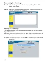
Страница 109: ...e specific connection Protocol Port Protocol type and Port number of the specific connection Disposition Accept or Deny Downloading the Traffic Logs The Administrator can backup the traffic logs regularly by downloading it to the computer Step 1 In the Traffic Log window click the Download Logs button at the bottom of the screen Step 2 Follow the File Download pop up window to save the traffic log...

Страница 110: ...ay clear on line logs to keep just the most updated logs on the screen Step 1 In the Traffic Log window click the Clear Logs button at the bottom of the screen Step 2 In the Clear Logs pop up box click OK to clear the logs or click Cancel to cancel it ...

Страница 111: ...nd description of the events from the Event Logs Entering the Event Log window Click the Event Log option under the Log menu and the Event Log window will appear The table in the Event Log window displays the time and description of the events Time Time when the event occurred Event Description of the event ...

Страница 112: ...w to save the event logs into a specific directory on the hard drive Clearing the Event Logs The Administrator may clear on line event logs to keep just the most updated logs on the screen Step 1 In the Event Log window click the Clear Logs button at the bottom of the screen Step 2 In the Clear Logs pop up box click OK to clear the logs or click Cancel to cancel it ...

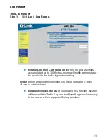
Страница 113: ...0Kbytes router will notify administrator by email with the traffic log and event log Note Before enabling this function you have to enable E mail Alarm in Administrator Enable Syslog Settings If you enable this function system will transmit the Traffic Log and the Event Log simultaneously to the server which supports Syslog function ...

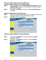
Страница 114: ... Step 2 Go to Log Log Report Check to enable Log Mail Support Click OK System Settings Enable Syslog Message Step 1 Check to enable Syslog Message Enter the Host IP Address and Host Port number to receive the Syslog message Step 2 Click OK to save new changes Disable Log Mail Support Syslog Message Step 1 Go to Log Log Report Uncheck to disable Log Mail Support Click OK Go to Log Log Report Unchec...

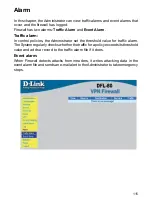
Страница 115: ...control policies the Administrator set the threshold value for traffic alarm The System regularly checks whether the traffic for a policy exceeds its threshold value and adds a record to the traffic alarm file if it does Event alarm When Firewall detects attacks from intruders it writes attacking data in the event alarm file and sends an e mail alert to theAdministrator to take emergency steps ...

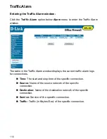
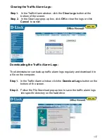
Страница 116: ...c Alarm window displays the current traffic alarm logs for connections Time The start and stop time of the specific connection Source Name of the source network of the specific connection Destination Name of the destination network of the specific connection Service Service of the specific connection Traffic Traffic in Kbytes Sec of the specific connection ...

Страница 117: ... the logs or click Cancel to cancel Downloading the Traffic Alarm Logs The Administrator can back up traffic alarm logs regularly and download it to a file on the computer Step 1 In the Traffic Alarm window click the Download Logs button on the bottom of the screen Step 2 Follow the File Download pop up box to save the traffic alarm logs into specific directory on the hard drive ...

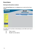
Страница 118: ...he Event Alarm window Click the Event Alarm option in the Alarm menu to enter the Event Alarm window The table in the Event Alarm window displays current traffic alarm logs for connections Time Log time Event Event descriptions ...

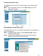
Страница 119: ...the screen Step 2 In the Clear Logs pop up box click OK Downloading the Event Alarm Logs The Administrator can back up event alarm logs regularly by downloading it to a file on the computer Step 1 In the Event Alarm window click the Download Logs button at the bottom of the screen Step 2 Follow the File Download pop up box to save the event alarm logs into specific directory on the hard drive ...

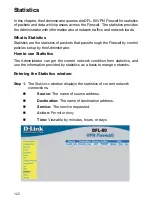
Страница 120: ...through the Firewall by control policies setup by the Administrator How to use Statistics The Administrator can get the current network condition from statistics and use the information provided by statistics as a basis to mange networks Entering the Statistics window Step 1 The Statistics window displays the statistics of current network connections Source The name of source address Destination T...

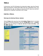
Страница 121: ... Status to check the DHCP lease time and MAC addresses for computers connected to the Firewall Interface Status Entering the Interface Status window Click on Status in the menu bar then click Interface Status below it A window will appear providing information from the Configuration menu Interface Status will list the settings for Internal Interface External Interface and the DMZ Interface ...

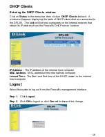
Страница 122: ...ddresses and their corresponding MAC addresses For each computer on the Internal External and DMZ network that replies to an ARP packet the DFL 80 will list them in this ARP table IP Address The IP address of the host computer MAC Address The MAC address of that host computer Interface The port that the host computer is connected to Internal External DMZ ...

Страница 123: ...n the Internal network that obtain its IP address from the Firewall s DHCP server function IP Address The IP address of the internal host computer MAC Address MAC address of the internal host computer Leased Time The Start and End time of the DHCP lease for the internal host computer Logout Select this option to log out from the Firewall s management interface Step 1 Click Logout Step 2 Click OK t...

Страница 124: ...ether a particular computer is connected to the Internet IP IP stands for Internet Protocol IP address uniquely identifies a host computer connected to the Internet from other Internet hosts for the purposes of communication through the transfer of packets IP has the following features Defining data packet structure packet is the basic unit of data exchange Addressing data packets Moving data betw...

Страница 125: ...exchange control messages to make sure a connection has been established this process is called handshaking TCP sets up control functions in the Flag field of the Segment Header Compared to UDP TCP is a very reliable protocol and uses PAR Positive Acknowledgment with Re transmission to guarantee that data from one host computer can reach the other host computer safely and correctly TCP IP Protocol...

Страница 126: ...he network There are four popular types of DoS attacks Bandwidth Consumption Attackers use wider bandwidth to flood victims bandwidth with garbage data For example using a T1 1 511Mbps leased line to attack 56k or 128k leased line or using several 56k sites to stuff a T3 45Mbps Resource Exhaustion This attack exhausts the victims systems resources such as CPU usage memory file system quota or othe...

Страница 127: ...strator to take emergency step in a timely fashion 5 Encrypt sensitive data to transfer them safely across internet Firewall has following restriction 1 Can t block hackers attacks from inside 2 Can t monitor connection that doesn t pass through firewall 3 Can t prevent new type of threats 4 Can t prevent virus s attacks Hackers and Crackers Hackers are those smart and aggressive programmers who a...

Страница 128: ... pass through routers to their destinations Packet Filtering Packet Filters check the headers of IP TCP and ICMP packets to gather information such as sources addresses source ports destination addresses and destination ports It also checks the relationships between packets to decide whether a packet is for normal connection In this way attacks can be detected and blocked Address Each address in A...

Страница 129: ...ing data in event alarm file and sends E mail to system manger to take emergent steps DMZ DMZ is the network between the firewall s external interface and routers DMZ s network number is allocated by ISPs For example when the network number an ISP provides is 210 71 253 128 and subnet mask is 255 255 255 240 Machines inside DMZ can have IP addresses ranged from 210 71 253 128 to 210 71 253 140 six...

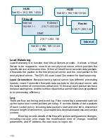
Страница 130: ...121234567 123456789012345678901234567890121234567 123456789012345678901234567890121234567 123456789012345678901234567890121234567 Load Balancing Load Balancing is a function that Virtual Servers provide It allows a Virtual Server to be mapped to more than one physical server which provides the specific service at the same time When a Virtual Server receives data packets it forwards the packet to t...

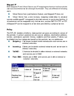
Страница 131: ...n pass according to values of the policies A policy s parameters are source address destination address service permission packets history statistics and flow alarms Policies can be divided into four categories based on the packets source addresses Outgoing Clients are located in internal networks and servers are in external networks Incoming Clients are located in external networks and servers ar...

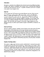
Страница 132: ... mangers can create new service groups in Service Group option of Service menu and assign desired services into groups Using address group and service group can greatly simply the policy creating process If there are ten different IP addresses that access five different server services such as HTTP FTP SMTP POP3 and TELNET Without the concept of address group and service group 10 5 50 policies are...

Страница 133: ...ifying the server s private IP address First we set the real IP address of an external network interface to the actual IP address of a Virtual Server Through IP translation of the Virtual Server outside users can access the servers of the internal networks Virtual Server owns another feature one to many mapping one real IP address on the external interface can be mapped into 4 internal virtual IP ...

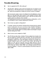
Страница 134: ... destroying the original system configuration the user can choose Export System Settings to Client in Settings under the Administration menu Users can upload the backup system configuration from the hard disk to the firewall in Import System setting from Client Q Q Which server can be installed in DMZ A The DFL 80 provides three Interface Ports to divide the networks into internal networks externa...

Страница 135: ... and password are both admin lower case The name admin can t be changed and the password should be modified and recorded at the time of installation 2 The internal Interface IP address is set to 192 168 1 1 in the factory The system administrator needs to change it to private IP address of the enterprise s internal networks Then set IP addresses of External and DMZ interface according to the real ...

Страница 136: ...UI click New Policy go to Add New Policy window click OK to complete the installation process Q In the Outgoing menu I set the source address to Inside Any the destination address to Outside any the service to HTTP and the action to Permit Why do the computers of the internal network still cannot access the Internet A Usually the DNS of the clients point to the DNS server outside of the firewall W...

Страница 137: ...e there any rules to follow when setting up administration policies A When setting up policies administrators need to follow small to big principle This means that when the source address destination address and service items of a policy is the subset of another policy it is necessary to set policy of the subset first For example the sequence to set policies for individual worker department and ev...

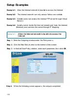
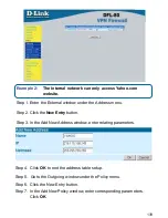
Страница 138: ...e 4 Install a server inside the Internal network and have the Internet External users access the server through IP Mapping Example 1 Allow the Internal network to be able to access the Internet Step 1 Enter the Outgoing window under the Policy menu Step 2 Click the New Entry button on the bottom of the screen Step 3 In the Add New Policy window enter each parameter then click OK Step 4 When the fo...

Страница 139: ...ess menu Step 2 Click the New Entry button Step 3 In the Add New Address window enter relating parameters Step 4 Click OK to end the address table setup Step 5 Go to the Outgoing window under the Policy menu Step 6 Click the New Entry button Step 7 In the Add New Policy window enter corresponding parameters Click OK ...

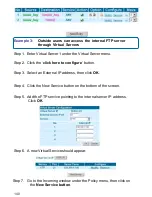
Страница 140: ...he click here to configure button Step 3 Select an External IP address then click OK Step 4 Click the New Service button on the bottom of the screen Step 5 Add the FTP service pointing to the internal server IP address Click OK Step 6 A new Virtual Service should appear Step 7 Go to the Incoming window under the Policy menu then click on the New Service button ...

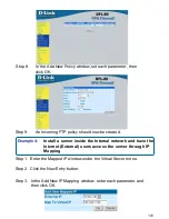
Страница 141: ...through IP Mapping Step 1 Enter the Mapped IP window under the Virtual Server menu Step 2 Click the New Entry button Step 3 In the Add New IP Mapping window enter each parameter and then click OK Step 8 In the Add New Policy window set each parameter then click OK Step 9 An Incoming FTP policy should now be created ...

Страница 142: ...spection SPI IntruderAttack Logging NAT Transparent DMZ Filtering Safety Emissions FCC Class B CE Mark Temperature Operating 32o to 140o F 0o to 60o C 95 maximum non condensing Humidity Diagnostic LED Power 1 COM Link Activity RJ 45 connector 10 100Mbps auto negotiation Auto crossover cable adaptation 1 WAN Link Activity RJ 45 connector 10 100Mbps auto negotiation Auto crossover cable adaptation 4...

Страница 143: ...dulation Techniques IP Sec IPAuthentication Header AH Internet Key Exchange IKE authentication and Key Management Authentication MD5 SHA 1 NULL DES 3DES Encryption Algorithm and their use with IPSec IP Encapsulating Security Payload ESP Internet Security Association and Key PPTP Server Client Weight 2 0 lbs 907g ...

Страница 144: ...upport over the Telephone 877 453 5465 24 hours a day seven days a week D Link Technical Support over the Internet http support dlink com email support dlink com Tech Support for customers within Canada D Link Technical Support over the Telephone 800 361 5265 Monday to Friday 8 30am to 9 00pm EST D Link Technical Support over the Internet http support dlink ca email support dlink ca When contactin...

Страница 145: ...ortion of the product Software will substantially conform to D Link s then current functional specifications for the Software as set forth in the applicable documentation from the date of original retail purchase of the Software for a period of ninety 90 days Warranty Period provided that the Software is properly installed on approved hardware and operated as contemplated in its documentation D Li...

Страница 146: ...ted by D Link with shipping charges prepaid Expedited shipping is available if shipping charges are prepaid by the customer and upon request Return Merchandise Ship To Address USA 53 Discovery Drive Irvine CA 92618 Canada 2180 Winston Park Drive Oakville ON L6H 5W1 Visit http www dlink ca for detailed warranty information within Canada D Link may reject or return any product that is not packaged a...

Страница 147: ...llation If this equipment does cause harmful interference to radio or television reception which can be determined by turning the equipment off and on the user is encouraged to try to correct the interference by one or more of the following measures Reorient or relocate the receiving antenna Increase the separation between the equipment and receiver Connect the equipment into an outlet on a circui...

Отзывы: