D-Link DCS-50 Скачать руководство пользователя страница 2

2

Ⅲ.


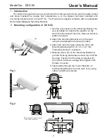
Fitting instructions for camera

4

6

5

2

3

1

4

1  Camera mounting platform

2  Terminal block assembly

3  Cable conduits PGB13.5 x 2

4  Captive retainning 1/4” Screws x 3

5  Heater wires, Ground wire

6  Ground wire

Fig.3

(A)

(B)

(C)

(D)

(C)

(H)

(G)

(F)

(E)

(G)

(J)

(I)

1. Unscrew the 3 captive Retaining Screws (C) and remove the Housing Cover (A) from 

    the Housing Base (B).

2. Release the 4 Keyhole Screws (F) and then slide and withdraw the Camera Platform 

    (G) from the Housing Base (B).

3. Mount the Camera (H) onto the Platform (G) using the 1/4” UNC Screw (I) supplied, ensuring  

that the Insulation Pad (J) is mounted between the Platform and the Camera. Always check 

that the Camera is firmly attached to the Platform.

4. Connect the Camera power cable to the rear Terminal Block (E) through the 

    first Cable Conduit (D) referring to the circuit diagram shown in section IV. for the 

    terminal designations.

5. Connect the video cable to the Camera through the second Cable Conduit(D). 

IMPORTANT NOTE:

ALWAYS UNPLUG THE TOP SECTION OF THE EARTH WIRE FROM THE BASE WIRE WHEN 

DISASSEMBLING THE HOUSING. REMEMBER TO PLUG THE TOP AND BOTTOM TOGETHER 

AGAIN WHEN REASSEMBLING THE HOUSING.

Ⅳ.


Wiring diagram

Fig.4 shows the internal wiring diagram of 

DCS-50 for the window demister. 

When necessary, a spare 6 way terminal 

block is provided at the rear of the enclosure 

for the camera and lens connections.

Circuit identified as follows:
TB.1        6 way terminal block

FTB.1      Fused terminal block

FS.1        3 Amp. Fuse

Fig.4 Wiring diagram of DCS-50

1

TB.1

N
E
L

FTB.1 FS.1

COVER EARTH

CHASSIS EARTH

ENCLOSURE BASE

SP

ARE

2
3
4
5
6

Содержание DCS-50

Страница 1: ...se the rear section of the Mounting Bracket D as a template for marking the position on the wall of the Mounting Holes H Remove drill to pattern required 2 Attach the Mounting Bracket arm to the wall using the rawlplugs and screws provided 3 Attach the main Housing enclosure K to the Mounting Bracket with 2 of 1 4 x 14 7 mm Trilobular screws F provided 4 Release Screw E on the Mounting Bracket to ...

Страница 2: ... Connect the Camera power cable to the rear Terminal Block E through the first Cable Conduit D referring to the circuit diagram shown in section IV for the terminal designations 5 Connect the video cable to the Camera through the second Cable Conduit D IMPORTANT NOTE ALWAYS UNPLUG THE TOP SECTION OF THE EARTH WIRE FROM THE BASE WIRE WHEN DISASSEMBLING THE HOUSING REMEMBER TO PLUG THE TOP AND BOTTOM...

Страница 3: ... purchased through the inventory clearance or liquidation sale or other sales in which D Link the sellers or the liquidators expressly disclaim their warranty obligation pertaining to the product and in that case the product is being sold As Is without any warranty whatsoever including without limitation the Limited Warranty as described herein notwithstanding anything stated herein to the contrar...

Страница 4: ...may not apply This Limited Warranty provides specific legal rights and you may also have other rights which vary from state to state Trademarks D Link is a registered trademark of D Link Systems Inc Other trademarks or registered trademarks are the property of their respective owners Copyright Statement No part of this publication or documentation accompanying this product may be reproduced in any...

Отзывы: