


DCM-200 USB/Ethernet Cable Modem
5
Identifying External Components
This section identifies all the major external components of the device. Both the front and rear panels are shown
below followed by a description of each panel feature. The indicator panel is described in detail in the following
section.
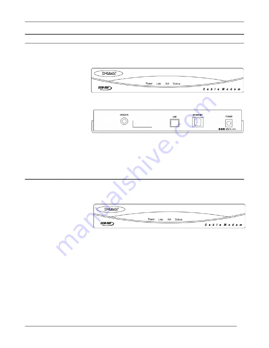
Front Panel
This figure shows the front
panel of the device.
LED Indicator Panel Refer to the next chapter, “
Understanding Indicators
,” for detailed information about
each of the DCM-200’s LED indicators.
Rear Panel
This figure shows the rear
panel of the device.
AC Power Connector - For the included power adapter, if you use a power adapter other than the one included
with the product, please make sure it has a DC output of 12V/1A.
Ethernet 10BASE-T Port - The 10BASE-T Ethernet port accepts Category 5 or better UTP cabling with an RJ-
45 connector used to connect the DCM-100 to a LAN device (hub, switch, PC, etc.).
Cable In This jack is used to connect the DCM-200 to the splitter. This connection is achieved using a length of
cable TV wire supplied by your cable company during installation.
USB Port Connect this port on the DCM-200 directly to your PC.
Understanding Indicators
Before setting up your
USB/Ethernet Cable Modem for
the first time, take a few minutes
to look over this section and
familiarize yourself with the
front panel LED indicators
depicted below.
Power
- This LED is lit red when the device is receiving power; otherwise, it is unlit.
Link
- This LED is lit green to indicate that a valid connection exists between the Ethernet port on the Cable
Modem and your PC. If it is unlit, there is no valid connection.
Act (Activity)
- A blinking green LED indicates that traffic activity is passing through your cable modem
port.
Status
– The Status LED will be “ON” solid when the cable modem is properly connected to the cable network
(ISP). *If your status light continues to blink, please contact your cable operator for further instructions.
NOTE:
If no lights come, check all of your connection to see if they are properly inserted.
Powering Up the First Time
You must allow at least 1 to 3 minutes to power up the first time because the DCM-200 must find and secure a
connection.


