background image


The CD-ROM included with your DFE-520TX is designed to make installation of necessary 
software a painless and trouble-free process. Simply click on the 

Install Drivers

 link, and an 

Installation Wizard will guide you through the process, no matter which operating system you’re 
running. The included Adobe Acrobat Reader, which is needed to read or print out your user 
manual, will also come in handy for many other applications.  

Simply follow the directions in the Wizard, and your DFE-520TX will be installed successfully in 
just a few minutes, allowing you to enjoy the many advantages of joining an Ethernet LAN.  

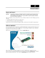
When the driver installation program (shown above) is complete, you can then install the PCI 
card inside your PC.  When you restart your PC, the DFE-520TX will be ready to use. 

Installing the Adapter 

1.


Shut down the computer, unplug its power cord, and remove the chassis cover. 

(

Important

: Opening the case of your computer may compromise the warranty of your computer. 

Consult the computer manufacturer before opening the case to ensure that you adhere to 
warranty guidelines. In some cases, you may need to have the DFE-520TX installed by your 
computer manufacturer.) 

2.


Insert the contact edge of the DFE-520TX card into the connector of any available PCI Bus 
Master expansion slot. Press the card firmly into the connector such that the card’s contacts 
are fully seated in the connector. 

3.


Install the bracket screw that secures the card to the computer chassis. 

4.


Replace the computer’s chassis cover. 

5.


Reconnect the computer’s power cord, and switch computer power on. If the BIOS section of 
your computer’s boot program is Plug-and-Play compliant, then at power-up the BIOS will 
automatically configure any newly installed DFE-520TX adapter. 

NOTE:   Due to a fault in some Plug-and-Play BIOS programs, occasionally a newly installed adapter is assigned an 

Interrupt Number which has already been assigned to another device. In such a case, the conflict of the 
Interrupt Number will cause faults in the behavior of both devices. Therefore, the user must run the CMOS 
Setup utility, and manually assign a non-conflicting Interrupt Number. 

Connecting the Network Cable 

Category 5 UTP cable qualifies for both 100BASE-TX Fast Ethernet and 10BASE-T Ethernet 
cabling rules.  The maximum length of any single cable segment is 100 meters. Please keep in 
mind, however, that the maximum cable run between any two stations in a collision domain is 
205m. 


Содержание 32-bit PCI Fast Ethernet Network Adapter...

Страница 1: ...D Link DFE 520TX 32 bit PCI Fast Ethernet Network Adapter Manual Second Edition June 2007 6DFE520TX 02G Printed in Taiwan RECYCLABLE ...

Страница 2: ...f Contents INTRODUCTION 1 System Requirements 1 Features 1 INSTALLATION 3 Unpack and Inspect 3 Installing the Adapter 4 Connecting the Network Cable 4 Software Installation 3 TROUBLESHOOTING 5 SPECIFICATIONS 6 ...

Страница 3: ...uirements Before installing the DFE 520TX check your system for the following minimum configuration requirements One of the following slot types An open PCI bus master slot 32 bit operating at 33MHz 32 MB of System Memory 150 MHz processor or faster The latest BIOS for your computer One of the following types of twisted pair network cabling Category 5 or better for 100Mbps Category 3 5 or better f...

Страница 4: ...e 5 kernel 2 6 Microsoft Windows XP XP x64 Macintosh OSX 10 2 x Microsoft Windows Server 2003 Netware Server 5 0 5 1 6 0 6 5 Microsoft Windows 2000 Netware Client 32 for DOS Windows 3 1x Windows 95 95 OSR2 98 98SE ME ODI Driver for DOS Windows NT 3 51 NT 4 0 NDIS2 Driver for DOS Windows for WorkGroup 3 11 Packet Driver for DOS Check http www dlink com for newest release of drivers ...

Страница 5: ...d DFE 520TX Drivers and Manual on CD ROM If any of these items are missing or damaged please contact your local reseller for replacement Software Installation You must install the driver software for your DFE 520TX before installing the PCI card into your PC Insert the CD into your PC s CD ROM drive It should begin running the driver installation program if you have auto execute enabled When the s...

Страница 6: ...he DFE 520TX installed by your computer manufacturer 2 Insert the contact edge of the DFE 520TX card into the connector of any available PCI Bus Master expansion slot Press the card firmly into the connector such that the card s contacts are fully seated in the connector 3 Install the bracket screw that secures the card to the computer chassis 4 Replace the computer s chassis cover 5 Reconnect the...

Страница 7: ...ble is employed for the network connection that the supporting hub is properly qualified for the application The DFE 520TX Adapter features one LED indicators Link Activity Steady green indicates good linkage between the DFE 520TX and its supporting server or switch Flashing green indicates activity transmitting or receiving within the adapter ...

Страница 8: ... Bus Master I O base address assigned by Plug and Play system Interrupt Number Assigned by Plug and Play system Physical Dimensions 4 73 inches L x 1 65 inches W 121mm L x 42mm W Environment Storage 25 to 55 C 13 to 131 F Operating 0 to 40 C 32 to 104 F Humidity 5 to 90 non condensing Power Consumption 0 4W ...

Страница 9: ...e for a period of ninety 90 days Software Warranty Period provided that the Software is properly installed on approved hardware and operated as contemplated in its documentation D Link further warrants that during the Software Warranty Period the magnetic media on which D Link delivers the Software will be free of physical defects The customer s sole and exclusive remedy and the entire liability o...

Страница 10: ...ny product that is not packaged and shipped in accordance with the foregoing requirements or that is determined by D Link not to be defective or non conforming What Is Not Covered The Limited Warranty provided herein by D Link does not cover Products that in D Link s judgment have been subjected to abuse accident alteration modification tampering negligence misuse faulty installation lack of reaso...

Страница 11: ...egistered trademarks are the property of their respective owners Copyright Statement No part of this publication or documentation accompanying this product may be reproduced in any form or by any means or used to make any derivative such as translation transformation or adaptation without permission from D Link Corporation D Link Systems Inc as stipulated by the United States Copyright Act of 1976...

Страница 12: ...Registration Register your D Link product online at http support dlink com register Product registration is entirely voluntary and failure to complete or return this form will not diminish your warranty rights ...

Страница 13: ...itzerland URL www dlink ch Greece URL www dlink gr Luxemburg URL www dlink be Poland URL www dlink pl Hungary URL www dlink hu Singapore URL www dlink intl com Australia URL www dlink com au India URL www dlink co in Middle East Dubai URL www dlink me com Turkey URL www dlink com tr Iran URL www dlink me com Pakistan URL www dlink me com Egypt URL www dlink me com Israel URL www dlink co il LatinA...

Отзывы: