background image


CEILING SERIES  

                              Manual del usuario / 

User's manual


9


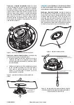
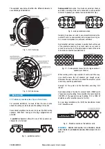
Step 5 – Screwing and fixing

:  to fix the assembly to the 

ceiling, the tabs have to be rotated and lowered. This is done 
by tightening the corresponding screws clockwise. The first 
quarter turn rotates the tab into position and out of the guide; 

the rest tightens the tab down onto the back of the ceiling 
surface. The process needs to be repeated for all four screws. 


Fig. 9 – fixing the speaker to the ceiling 


Fig. 10 – fixing system: when tightening the screw the 

mounting tab comes down, pressing the plastic support 

against the ceiling. 


Step 6 – Replace the grille

:  once the speaker is fixed to the 

ceiling, this is the only operation left. 


Push the grille into place until fixed. You will need to use the 

adhesives stripes provided.


Note: the grille shows some degree of resistance to be 
removed. Fixing is by contact, so there is little clearance 

between its inner diameter and the inner support, so that 
some force needs to be applied when removing it.  


3. DAS AMPLIFIERS TO BE USED 


For model CL-5T installations, some DAS Audio amplifiers 
provide 70 and 100V outputs. 


Model Line 

(V) 

Mode Power 

(W) 

E-12 50 Stereo 

650 

E-20 70 Stereo 

960 

E-12 100 Bridge 

1220 

 
To calculate the required amplifier power for a 70 or 100V line, 

simply sum the input power selection of all speakers 
connected to a given amplifier channel. Example: for a 70V 
line with 40 units of CL-5T (with multi-tap transformer that 
offers a selection of 1.5,3 and 6W) which are all set to 6W, 
the total speaker power handling will be 40x6=240W. The 

only requirement is that the total speaker power is below the 
amplifier’s output power. 


4. MAINTENANCE, USE 

 
No maintenance is needed for the products in this manual if 
they have been installed correctly and following the 
instructions in this manual. 

 
Some usage tips follow: 
 
The best maintenance for a speaker is its correct use, i.e., 
within the design parameters. It is important not to utilise 

amplifiers that are too large when compared to the speaker 
power. In general, it is recommended that you use an amplifier 
with an output that is 100% to 150% of the speaker's average 
(RMS) power rating. That way we have headroom for the 
dynamics of real music and vocal signals, and at the same 

time deliver a cleaner signal to the speakers that will result in 
a more reliable system. Avoid using too small an amplifier. 
 
The clip light of your amplifiers should never be on 
continuously. This will distort the signal and may damage the 

speakers. In fact, severe clipping is an easy way to burn a 
speaker’s voice coil. At most, the clip light could blink 
occasionally. When clipped, signals sound distorted and 
produce listening fatigue quickly. 

 
Never use a total impedance load that is lower than the 
lowest impedance that an amplifier will take. Virtually all 
professional amplifiers will accept loads down to four ohms 
safely in stereo mode. Many are rated for two ohm loads but 

often will run into overheating protection when used this way, 
particularly in high ambient temperature and high output 
power applications. Never connect more speakers to an 
amplifier's channel than it will take, i.e. do not load a channel 
with total impedance that is lower than the minimum load 

specified by the manufacturer.


Содержание Ceiling Series

Страница 1: ...MANUAL DEL USUARIO USER S GUIDE Ceiling Loudspeakers ...

Страница 2: ...substitution may affect safety No exponga este equipo a lluvia o humedad Do not expose this device to rain or moisture Véase el manual de instrucciones para la conexión e instalación Conserve estas instrucciones Siga todas las advertencias Lea todas las instrucciones Refer to instructions manual for connection and installation Keep these instructions Heed all warnings Follow all instructions Limpi...

Страница 3: ...e permite acceder por la parte frontal a cada uno de los componentes que constituye el producto para retirarla se precisa un objeto puntiagudo que pueda ser introducido en cualquiera de los orificios Para más detalles acerca del procedimiento para desmontar la reja consultar el apartado 3 2 del presente manual ATENCIÓN TENGA PRECAUCIÓN CON EL OBJETO PUNTIAGUDO PARA NO DAÑAR EL ALTAVOZ AL EXTRAER L...

Страница 4: ...tanto la realización de orificios circulares en los lugares destinados a albergarlo como el cableado para cada una de las unidades existentes Para realizar las instalaciones con los altavoces de techo de D A S Audio se pueden emplear amplificadores convencionales pudiendo realizar por lo tanto dos configuraciones básicas con productos de 8 ohmios de impedancia Configuración en paralelo que permite...

Страница 5: ...e las etapas que es necesario seguir para llevar a cabo la instalación completa del producto Se ha de tener presente como paso previo a los que a continuación se detallan el cableado de toda la instalación por el techo dejando los terminales necesarios en los puntos donde se ha de instalar un altavoz Primer paso Quitar reja del altavoz Antes de comenzar la instalación se debe retirar la reja del a...

Страница 6: ...o del corte efectuado Introducir el conjunto en el orificio cuidando que cada una de las 4 pestañas giratorias que sirven para fijarlo al techo quede en posición tangencial al corte de otra manera no se podrá colocar el conjunto ya que las propias pestañas lo impedirían Figura 8 conexión de terminales posicionamiento del altavoz ATENCIÓN SUJETE SIEMPRE EL ALTAVOZ POR EL SOPORTE DE PLÁSTICO DEL MIS...

Страница 7: ...or a 240W con tensión de línea de 70V 4 MANTENIMIENTO PRECAUCIONES No es necesario el mantenimiento de los productos descritos en el presente manual siempre y cuando se hayan instalado de forma correcta y siguiendo las instrucciones del manual A continuación se describen algunas precauciones que pueden resultar útiles para el usuario Es necesario recordar al usuario que el mejor mantenimiento que ...

Страница 8: ...X should not be utilised All models feature a removable protective grille with a DAS logo which allows access to the front of the loudspeakers For removal a pointy object needs to be introduced on a grille hole For further detail consult section 3 2 of this manual WARNING BE CAREFUL NOT TO DAMAGE THE CONE WITH THE POINTY OBJECT WHEN REMOVING THE GRILLE Connection terminals are spring loaded and co...

Страница 9: ...series parallel can be increased as long as 4 or more ohms impedance is achieved as follows Each amplifier will drive two loads in parallel Each will consist of the parallel connection of as many loads as we want to connect in series Each of the latter loads consists of the units to be series connected see illustration Fig 4 1 Series parallel connection of a large number of speakers per channel Wh...

Страница 10: ...f the speaker when painting Therefore the cut out may be scribed using the template provided or by drawing a circumference of the diameter in table 1 Once the hole is cut you may need to pull down the cables so they are accessible for connection Fig 6 circular cut out installation wiring Step 3 Terminal connection the speakers terminals are spring loaded Watch the colour coding for polarity For co...

Страница 11: ...dling will be 40x6 240W The only requirement is that the total speaker power is below the amplifier s output power 4 MAINTENANCE USE No maintenance is needed for the products in this manual if they have been installed correctly and following the instructions in this manual Some usage tips follow The best maintenance for a speaker is its correct use i e within the design parameters It is important ...

Страница 12: ...th Court Miami FL 33166 U S A Tel 305 436 0521 Fax 305 436 0528 D A S Audio of America Inc C Islas Baleares 24 46988 Fuente del Jarro Valencia SPAIN Tel 96 134 0525 Tel Intl 34 96 134 0860 Fax 96 134 0607 Fax Intl 34 96 134 0607 D A S AUDIO S A US 015 01d ...

Отзывы: