
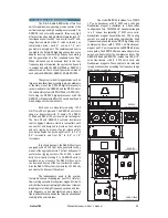


A sound system should be switched on
sequentially. Switch on the self-powered unit last in
your sound system. Switch on the sound sources
such as CD players or turntables, then the mixer, then
the processors, and finally the self-powered unit. If
you have several units, it is recommended that you
switch them on sequentially one at a time.
Follow the inverse order when switching off,
turning self-powered units off before any other
element in the sound system.
Mute all signal sources before switching the
unit on or off.
It is recommended that the red
LED
indicators are not lit continuously; at most it should
blink only occasionally.
If you wish to have a visual indication at the
mix position of whether the LIMIT LEDs are lighting,
during equipment set-up, closely observe what mixer
VUmeter level corresponds to the level that lights the
enclosure's LIMIT LEDs. That level that should not be
exceeded during the event.
LIMIT
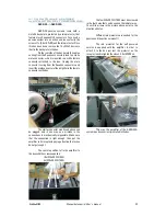
Due to their high efficiency, the Aero Series
amplifiers generate very little residual heat and
therefore do not need a fan for cooling. In normal use,
the amplifier panel will be warm to the touch.
If the unit stops playing (or just the mid-high
or the bass sections), the amplifier's overheating
protection may be activated to protect the
components from thermal damage.
Overheating may be due to insufficient
cooling, or to very aggressive use in extremely hot
conditions. Do not use the unit in proximity to high
power lights.
Once the amplifier cools down, it switches
back on automatically. If the unit should shut down
again, try reducing the volume a notch to avoid
overheating.
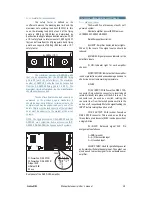
3.7
INDICATORS
OVERLOAD
(LIMIT)
3.6 SWITCH ON-OFF
3.8 OVERHEATING
3.10 LOW MAINS VOLTAGE
If mains voltage falls below the shutdown
voltage for the unit, it will stop playing. When
acceptable levels are regained, the unit will switch
back on automatically.
3.9 ECUALIZATION
The AERO-38A can be used full-range. Full-
range use is only recommended for applications
where low SPL level and no bass reinforcement is
adequate. To use it in this mode simply plug the mixer
into the enclosure's input.
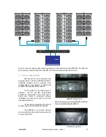
The most common use will be combined
with the AERO-218A (AERO-182A). In this case
different outputs of the mixing console will be used
with the AERO-38A and the SUBS. Both sub systems,
AERO-182A and AERO-218A include signal treatment
in the amplifiers extending their frequency range up to
85Hz. As well, the amplifier of the AERO-38A
incorporates signal treatment which provides
frequency range extension down to 60Hz. Due to this
overlap between 60-85Hz the use of an
to control and adjust the phase of the subs
external
delay
is
recommended.
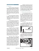
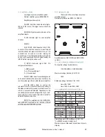
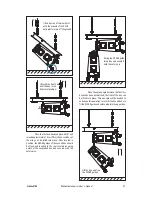
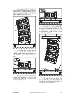
3.11 CONNECTIONS
AERO-38A
Mezclador/
Mixer
Retardo/
Delay
AERO-182A
Procesador/
processor
The
connector is an output XLR
in parallel with the input connector and is useful for
daisy chaining the input signal to a number of boxes,
connecting them in parallel.
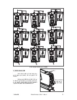
The number of units that can be linked this
way depends on the output impedance of the
equipment driving the enclosure, such as the mixer or
processor. Typically, to avoid signal degradation, the
maximum number that can be daisy chained is given
by the formula Zc>10Zs, where Zc is the load
impedance and Zs is the output impedance of the
equipment driving the enclosure (mixer, console, etc).
For instance, a mixing console with 100 ohm output
impedance allows daisy chaining 20 boxes, when the
input impedance of the cabinets is 20K ohm.
LOOP THRU
Aero-38
Manual del usuario/
User´s manual
50
The units do not need extreme EQ. Avoid
high levels of gain on the equalizers. Gain values
above +6 dB on a console's EQ are not
recommended.
Содержание AERO-38 series
Страница 1: ...Manual del Usuario User s Guide AERO 38 series...
Страница 20: ...Manual del usuario User s manual 60 Aero 38...