PSoC Analog Coprocessor Pioneer Kit Guide, Doc. # 002-11190 Rev. *B
32
Kit Operation
3.2
Flexible Prototyping
PSoC Analog Coprocessor Pioneer Kit is footprint-compatible with Arduino Uno R3 shields and
baseboards. It can interface with shields, or be used as a shield for any host processor board. It
includes onboard KitProg2 programmer and debugger with ARM CMSIS-DAP.
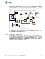
All the analog sensors on the PSoC Analog Coprocessor Pioneer Kit can be disconnected from the
PSoC device or the header by removing the 0
resistors.
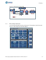
shows the I/Os of the PSoC
Analog Coprocessor connected to both the sensors as well as the headers through the 0
resistors.
lists all the 0
resistors used to connect PSoC pins to sensors and the headers. If a PSoC
pin is required to be used from the header for some other purpose than the onboard sensor, then the
pin can be disconnected from the sensor by removing the corresponding 0
resistor.
Figure 3-15. Connection Between Sensors, Port Pins, and Headers
Table 3-3. List of 0
Resistors Connecting PSoC Pins to Sensors and Headers
Pin
Sensor
Where on Sensor Circuit
0
for
sensor
Header
0
for
header
P2[0] PIR motion sensor
HPF at output of PIR sensor
R54
J6.9
R143
P2[1] PIR motion sensor
Feedback resistor for first-
stage Amplifier
R131
J2.9
R132
P2[2] PIR motion sensor
HPF between first-stage and
second-stage amplifier
R156
J6.8
R157
P2[3] Ambient light sensor
Feedback resistor of TIA
R82
J4.4
R160
P2[4] Ambient light sensor
Photo Diode Anode
R134
J3.1
R159
P2[5] Ambient light sensor
VREF
R161
J2.8
R162
P3[5] Thermistor
Junction of thermistor and
reference resistor
R83
J2.10
R4
P3[6] Thermistor
VSSA
R87
J6.6
R7
P3[7] Thermistor
Reference resistor
R142
J2.6
R141
P1[3] Thermistor
VREF
R90
J3.8
N/A (Direct)
P1[0] Inductive proximity sensor
VREF
R146
J4.7
R123
P1[1] Inductive proximity sensor
HPF
R81
J4.6
R121
P1[2] Inductive proximity sensor
Input of LPF
R124
J4.5
R127
PSoC Analog Coprocessor
Px.y
Sensor
Header
0
Ω
0
Ω


