


Design Considerations
AN64846 - Getting Started with CapSense
®
Doc. No. 001-64846 Rev. *X
67
Table 3-8. Proximity Sensor Layout Recommendations
Details
Minimum
Recommendation
Proximity sensor
loop diameter or
diagonal
The sensor loop diameter or diagonal should be equal to or
greater than the required proximity-sensing distance if the ALP
filter is disabled.
If the ALP filter is enabled, the sensor loop diameter or diagonal
should be equal to or greater than half of the required proximity-
sensing distance.
Start with a sensor loop diameter or
diagonal equal to the required
proximity-sensing distance and
increase the diameter or diagonal
until the required proximity-sensing
distance is achieved.
Proximity sensor
trace width
1.5 mm
1.5 mm
Parasitic capacitance of the sensor:
The proximity-sensing distance depends on the ratio of the C
F
to the C
P
.
The proximity-sensing distance increases with an increase in the C
F
/C
P
ratio. For a given sensor size, the value of
C
F
depends on the distance between the sensor and the target object. To maximize this ratio, you need to increase
C
F
and decrease C
P
. The C
P
of the sensor can be minimized by selecting an optimum sensor area, reducing the
sensor trace length, and minimizing the coupling of sensor electric field lines to the ground.
To reduce the coupling of sensor electric field lines to the ground, drive the hatch fill in the top and bottom layer of
the PCB (if there is any) with the driven-shield signal. A hatch fill that is connected to the driven-shield signal is
called a “shield electrode.” The driven shield signal is a replica of the sensor signal.
For shield electrode layout guidelines, see
Shield Electrode and Guard Sensor
To minimize the sensor trace length and, thereby, the sensor C
P
, place the CapSense device as close as possible
to the sensor.
Nearby floating or grounded conductive objects:
The proximity-sensing distance reduces drastically if there is
any floating or grounded conductive object nearby. The following factors cause the proximity-sensing distance to
reduce drastically when conductive objects are placed close to the proximity sensor:
The C
P
of the sensor increases. Larger sensor C
P
often requires reducing the sensor switching frequency,
causing the proximity-sensing distance to decrease.
A grounded conductive object catches a part of the sensor electric field and reduces the capacitance added
by the target as shown in
You should either remove the nearby conductive object or use a shield electrode to isolate the proximity sensor
from the conductive object. The influence of a nearby metal surface on the proximity sensor is reduced by placing
a shield electrode between the proximity sensor and the metal object, as shown in
. For layout
recommendations on shield electrode, refer to the
Shield Electrode and Guard Sensor
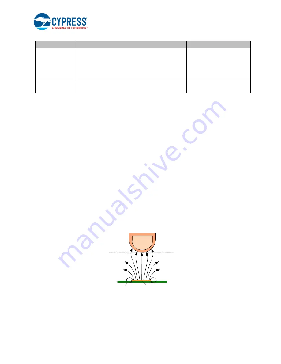
Figure 3-40. Electrical Field Propagation for a Single Sensor Configuration without a Metal Object
Finger
Detection
distance
PCB
Sensor


