


9
used to send commands directly to the Receiver.
Note: RS-232 bypass requires both the Transmitter and Receiver to be set
to “Bypass” mode.
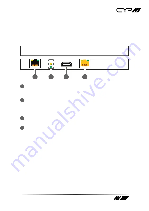
6.2 Rear Panel
CAT5e/6/7 IN
HQ
STD
HDMI OUT
LAN
1
3
2
4
1
LAN:
Connect to an Ethernet supporting device or to your local
network, as appropriate, to extend the network to both ends of the
HDBaseT connection.
2
HQ & STD LEDs:
These LEDs illuminate to indicate which AVLC mode
will be used when AVLC is required. The lower green LED indicates that
AVLC will use HQ (High Quality) mode. The upper yellow LED indicates
that AVLC will use STD (Standard) mode.
3
HDMI OUT:
Connect to an HDMI TV, monitor or amplifier for digital
video and audio output.
4
CAT5e/6/7 IN:
Connect to a compatible, 48V PoH supplying, HDBaseT
Transmitter with a single Cat.5e/6/7 cable for transmission of all data
signals as well as to power the unit.
Содержание PUV-1830RX-AVLC
Страница 1: ...PUV 1830RX AVLC HDBaseT HDR Receiver 4K HDCP2 2 PoH LAN OAR 18Gbps OPERATION MANUAL ...
Страница 2: ......


