9
6. OPERATION CONTROLS AND FUNCTIONS
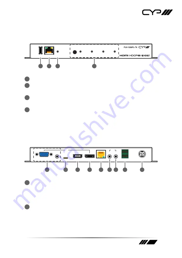
6.1 Front Panel
SERV. CONTROL
SELECT
VGA
USB-C
HDMI
DP
POWER
1
2
3
4
1
SERV. Port:
This port is reserved for firmware update use only.
2
CONTROL Port:
Connect directly, or through a network switch, to
your PC/laptop to control the unit via Telnet/WebGUI.
3
POWER LED:
This LED will illuminate to indicate the unit is on and
receiving power.
4
SELECT Button & VGA/USB-C/HDMI/DP LEDs:
Press the Select
button to sequentially switch through the available inputs. The
currently selected input’s LED will illuminate green. The LEDs will
illuminate red to indicate inputs that have live sources but are not
currently selected.
6.2 Rear Panel
VGA
AUDIO
USB-C
HDMI
DP
IN
IR
CAT5e/6/7 OUT
OUT
IN
RS-232
DC 24V
TX RX G
BYPASS
CONSOLE
1
2
3
4
5
6 7
8
9
1
VGA IN Port:
Connect to VGA source equipment such as a PC or
laptop.
AUDIO IN Port:
Connect to the stereo analogue output of the device
connected to the VGA input port.
2
USB-C IN Port:
Connect to USB Type-C video source equipment such
as a PC or laptop.
Note: Not all devices with USB Type-C ports can support video output.
Please verify that the device supports video output from the USB Type-C
port before connecting it.


