4
6.2 Rear Panel
MODE
LINK
MODE
LINK
MODE
LINK
IR IN
IR OUT
LAN
2
3
1
CAT5e / 6 / 7 OUT
1
2
3
4
1
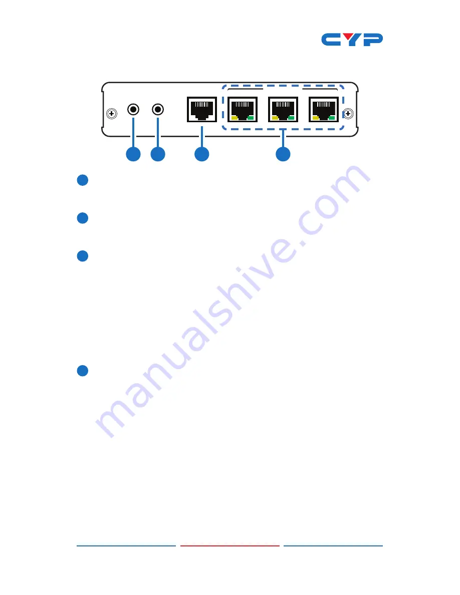
IR IN:
Connect the supplied IR Receiver cable for IR signal
reception. Ensure that remote being used is within the direct line-
of-sight of the IR Extender
.
2
IR OUT:
Connect the supplied IR Blaster cable for IR signal
transmission. Place the IR Blaster in direct line-of-sight of the
equipment to be controlled.
3
LAN:
Connect to an active network for LAN serving. When any
compatible LAN equipped receivers are connected, this allows
the network access (including internet access if available) to be
shared. Connect any Ethernet equipped device e.g. a Smart TV
or games console to the LAN port of a receiver for that device to
share the network/internet access.
Warning: DO NOT connect the LAN connection with any of the
CAT5e/6/7 outputs, doing so may trigger a power shut down and
may damage the device.
4
CAT5e/6/7 OUT 1~3:
Connect to CAT5e/6/7 to HDMI Receivers (with
or without PoE) with a single CAT5e/6/7 cable each to extend the
HDMI signal up to 100 m.
MODE LED:
This LED will illuminate when the power is connected.
LINK LED:
This LED will illuminate when connected to a Receiver unit
that is connected to a TV/monitor that is displaying the signal.
Содержание CHDBT-1H3CE
Страница 2: ......
Страница 14: ......
Страница 15: ......
Страница 16: ...Home page http www cypress com tw CYPRESS TECHNOLOGY CO LTD 20130531MPM CHDBT 1H3CE ...


