CyberView MD-19QD Скачать руководство пользователя страница 12

Page 12 -- ML24V02A -- www.EclipseRackmount.com
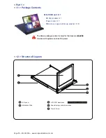


MD-19QD

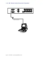
 < 4.1 > QD  Connection

< Part 4 >  Quad Display Connection  &  Operation
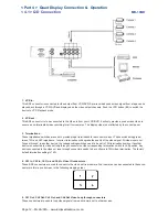
1.  VCR in :


This BNC connector is connected to video output from VCR/DVR. A pre-recorded quad screen signal from a tape can be 
played back through a VCR/DVR and displayed on the video output channels. Push the VCR button (#2) to switch the 
device to VCR Playback mode.   

2.  VCR out :        


This BNC connector is to be connected to the Video in from your VCR/DVR. It will only provide a quad screen video to 
ensure an un-interrupted video recording for all four cameras. The display video is not affected by the control panel.
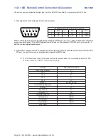
3.  Terminations :


These impedance switches are used to provide proper termination for each camera input. These switches toggle be-
tween 75

Ω

 and Hi-Z impedance.  Incorrect termination will degrade the quality of the video signal. All video inputs not 

“looped through” to another device, the corresponding switches need to be set to 75

Ω

 termination position. If another 

device is connected to video out loop through connector set the corresponding termination switch to Hi-Z position. Any 
device connected to the video out loop through connectors needs to be confi gure to 75

Ω

 video termination. The factory 

default termination setting is 75

Ω

.

4.  Ch1 In, Ch2 In, Ch3 In, and Ch4 In Video IN connectors

 :                                                                                              

These BNC connectors are used to connect to the video out from camera. Four cameras can be connected to these con-
nectors to form a quad screen in the following mapping order.

5.  Ch1 Out, Ch2 Out, Ch3 Out, and Ch4 Out Video Loop through connectors

 :                                                              

These connectors are used to loop video signals from each camera out to other devices. 

1

2

3

4


Содержание MD-19QD

Страница 1: ...ual ML24V02A Generation 4 www EclipseRackmount com User Manual Designed Manufactured by Austin Hughes and Distributed by Eclipse Rackmount Inc 1U 19 Quad Display Drawer MD 19QD Options Available DC Po...

Страница 2: ...e personnel should open the chassis Opening it yourself could damage the equipment and invalidate its warranty If any part of the equipment becomes damaged or stops functioning have it checked by qual...

Страница 3: ...P 4 5 P 6 Part 1 MD 19QD 1 1 Package Contents 1 2 Structure Diagram Dimensions 1 3 Installation Contents P 1 P 1 2 P 3 Contents Quad Display Connection Operation 4 1 QD Connection 4 2 QD ALARM Connect...

Страница 4: ...not made to clean monitors and monitor screens can scratch the LCD display or strip off the finish Do not spray any kind of liquid directly onto the screen or case of your monitor Spraying liquids di...

Страница 5: ...l membrane Thumb Screw 1 1 Package Contents Part 1 MD 19QD unit X 1 6ft VGA cable X 1 Power cord X 1 M6 screw cage nut cup washer X 8 1 2 Structure Diagram The above package content is only for the ba...

Страница 6: ...accessories options such as DC power 1 2 Dimensions Front View Side View UNIT mm 1mm 0 03937 inch Top View Model Product Dimension W x D x H Packing Dimension W x D x H Net Weight Gross Weight MD 19Q...

Страница 7: ...n Step 3 Insert the left and right rear mounting brackets into the display drawer Step 1 1 3 Installation How to install Installation Slides Step 2 Measure the depth of the front and rear mounting rai...

Страница 8: ...ess typ 250 Contrast Ratio typ 1000 1 Color 16 7 M Viewing Angle L R U D 80 80 80 80 Response Time ms 5 Dot pitch mm 0 294 Display Area mm 376 32H x 301 05V Surface treatment Haze 25 Hard coating Surf...

Страница 9: ...860 x 140 mm 23 4 x 33 9 x 5 5 inch Net Weight 12 5 kgs 28 lbs Gross Weight 18 5 kgs 41 lbs Applicable Format VGA Input PC Signal 1280 x 1024 x 60 75Hz 1280 x 960 x 60Hz 1280 x 760 x 60 75Hz 1152 x 8...

Страница 10: ...n for 5 seconds Display the OSD menu Power on off LCD Power light Green On Orange Power saving Membrane Switch Function OSD Conf guration Page Image for the brightness contrast color temp red green an...

Страница 11: ...tage 12 Volt 24 Volt 48 Volt Input range 9 18V 18 36V 36 75V Input current No load 50 mA 50 mA 50 mA Full load 4950 mA 2450 mA 1220 mA Output rating Output voltage 12 Volt 12 Volt 12 Volt Output curre...

Страница 12: ...These switches toggle be tween 75 and Hi Z impedance Incorrect termination will degrade the quality of the video signal All video inputs not looped through to another device the corresponding switche...

Страница 13: ...l allow you to use an ordinary VCR to record for longer period of time Combined with alarm sensor detection the VCR will record only when an alarm sensor is activated If more than one sensor have been...

Страница 14: ...ollowing 1 Connecting the Alarm Reset In contact pin 5 of the female type 9 pin D sub connector 8 to GND 2 The Alarm Duration time elapses 3 If the device is operated under Security Lock ON mode Push...

Страница 15: ...age 15 ML24V02A www EclipseRackmount com h i z 1 2 3 4 75 IN OUT RS 232 ALARM dc 12V 1amp monitor vcr I O RS 232 Cable Wire Computer Remote Keypad Rear Panel 4 3 QD Remote Control Connection Operation...

Страница 16: ...the male type 9 pin D sub connector on the real panel from it RS 232 port to control this device using standard uppercase ASCII codes 2 1 The ASCII command codes for the quad are listed in the table...

Страница 17: ...continuously for more than 4 seconds to clear the alarm 3 Setup menu is switched ON by sending VCR DVR and Lock button codes together 4 Text Select and Cursor Control functions can be performed only u...

Страница 18: ...ns of the unit BYTE 1 Status code for normal operation modes Channel Select 1110 CH1 1101 CH2 1011 CH3 0111 CH4 Display Mode 0 Quad screen display 1 Full Screen display Auto sequencing mode 0 Auto seq...

Страница 19: ...CH4 activated BYTE 2 Status code for alarm operations The first 4 bits show the sensor activated alarm status of each channel next 4 bits show the video loss alarm status of each channel The digit 1...

Страница 20: ...p buttons Push these two buttons simultaneously to get into Menu Setup mode and display page 1 of system setup menu Push these two buttons simultaneously again to display page 2 of the setup menu Use...

Страница 21: ...8 characters may be entered for each video channel The available alphanumeric characters are 0 1 2 3 4 5 6 7 8 9 A B C D X Y Z space 1 2 DWELL Time setup The Dwell time menu permits setting the dwell...

Страница 22: ...nected type of sensor a blinking message will display In this case the buzzer will be activated when you exit the setup operation 2 2 Alarm Sensitivity Alarm sensitivity can be programmed to different...

Страница 23: ...the still screen mode is desired first turn the quad display button 4 to ON to set the unit to display in the quad mode At this time you may press any of the four channel selection buttons 5 to freez...

Страница 24: ...yback mode Under this mode if the device is on quad display mode a pr recorded quad display video in the tape will be shown on the screen If the device is in Full screen display mode push any channel...

Страница 25: ...Live Monitor 1 0 Vpp 75 Ohm x 1 Loop Through Out 1 0 Vpp 75 Ohm x 4 VCR Output 1 0 Vpp 75 Ohm x 1 Auto Gain Control Yes Time Date Yes On Screen Display Yes Camera Title 8 Character Title Display Forma...

Страница 26: ...pecifications without prior notice and assumes no responsibility for any error which may appear in this publication All brand names logo and registered trademarks are properties of their respective ow...

Отзывы: