CyberPower BPE240V30ART3U Скачать руководство пользователя страница 5

Copyright ©  2017 Cyber Power Systems, Inc.


HARDWARE INSTALLATION


4


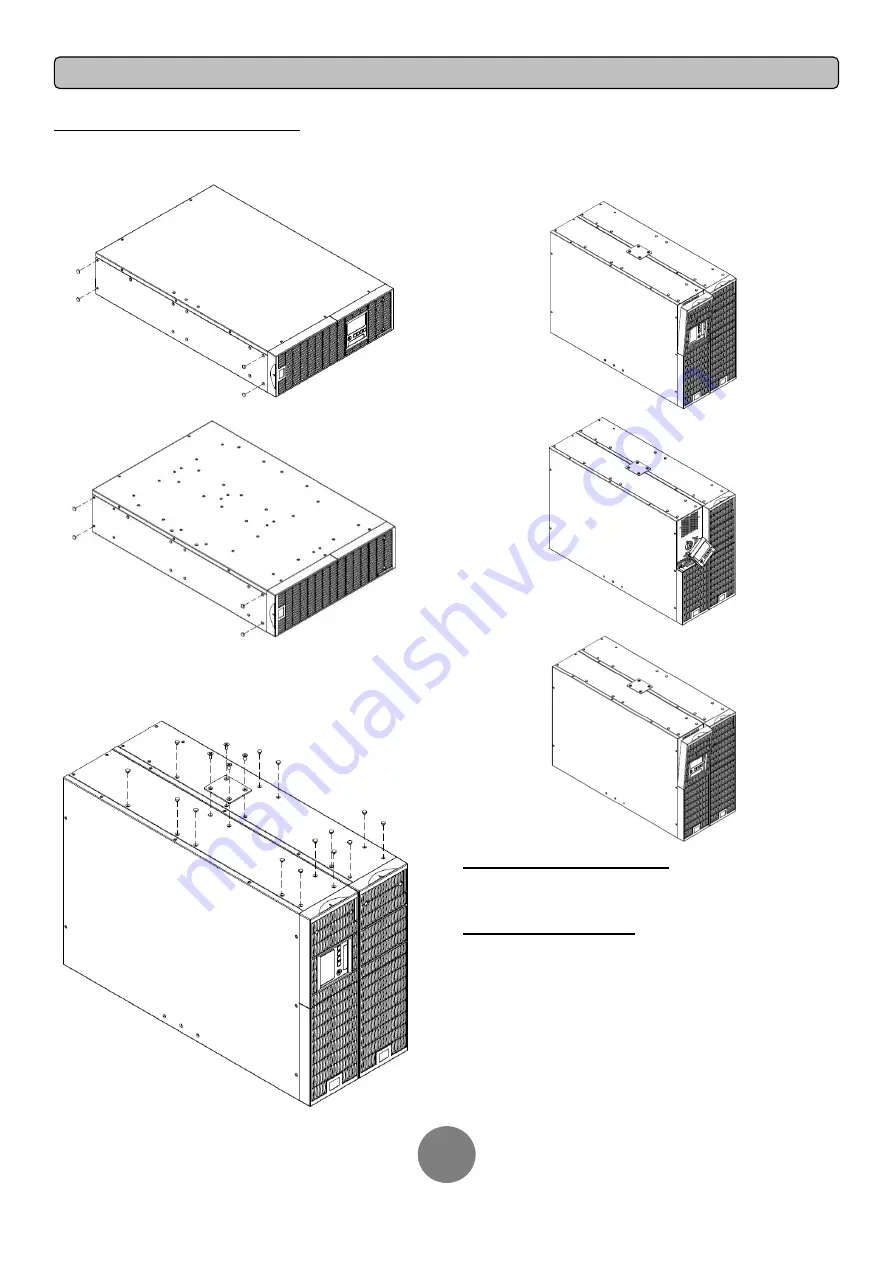
VERTICAL/TOWER INSTALLATION

Step 1: Adhere the rubber feet on the bottom side of base stands


Adhere the protective rubber feet on the bottom side of UPS and EBM. 

Step 2: Attach the base stands and attach the dust covers 

Secure the tie bracket with the screws (M5X7*4pcs).  Insert dust covers 
into the screw holes that are not being used. 

Step 3: Rotate the Multifunction LCD Module 

Unscrew the upper panel of the UPS. Separate the upper panel from the 
UPS. Gently lift the LCD module out. Rotate it to the tower orientation. 
Reinstall it for a tower configuration.


ELECTRICAL INSTALLATION


After completing the hardware installation of the UPS, you are now ready 
to plug in the UPS and connect your equipment. 

SAFETY PRECAUTIONS 

CAUTION!   

Installation environment should be in a temperature and 

humidity controlled indoor area free of conductive contaminants. Do not 
install this EBM where excessive moisture or heat is present (Please see 
specifications for acceptable temperature and humidity range). 

CAUTION!   

Never install an EBM, or associated wiring or equipment, 

during a lightning storm. 

CAUTION!   

Do not work alone under hazardous conditions. 

CAUTION!   

In case of the risk of electric shock, do not remove the top 

cover. 

CAUTION!   

The battery can energize hazardous live parts inside even 

when the AC input power is disconnected.

Содержание BPE240V30ART3U

Страница 1: ...User s Manual EXTENDED BATTERY MODULE EBM BPE240V30ART3U BPE240V50ART3U Cyber Power Systems Inc www cyberpower com K01 0000209 02...

Страница 2: ...with a 240VDC external connection Additional parallel connected Battery modules provide the UPS for a longer extended runtime operation Battery module User s manual Register card Rackmount left rail R...

Страница 3: ...attach the mounting brackets RACKMOUNT INSTALLATION Step 1 Remove the dust covers Remove the dust covers 10pcs from the screw holes Step 2 Rackmount ears hanging brackets installation Attach two rackm...

Страница 4: ...of the rack with two M5X6L screws and two plastic washers Step 5 Place and secure the UPS on the rails Slide the hanging brackets on the UPS into the rails mounted in the rack with the front of the un...

Страница 5: ...ll it for a tower configuration ELECTRICAL INSTALLATION After completing the hardware installation of the UPS you are now ready to plug in the UPS and connect your equipment SAFETY PRECAUTIONS CAUTION...

Страница 6: ...is input connector to daisy chain the next Battery module Remove the connector cover for access 6 Output Cable Use this output cable to connect the Battery module to the Power module or to the next Ba...

Страница 7: ...two screws to remove the battery cable retention bracket of the 1st battery module Step 3 Use the output cable of the 2nd Battery module to connect the 2nd Battery module to the 1st Battery module St...

Страница 8: ...s to scroll to the EBP Number option 5 Press the ENTER button to select the EBP Number submenu The first configuration number will be displayed on the second column of LCD display 6 Press the and butt...

Страница 9: ...erminals Replacement Batteries Please refer to the front side of the Battery module for the model number of the correct replacement batteries For battery procurement log onto www CPSww com or contact...

Страница 10: ...45 Sealed Maintenance Free Yes Hot Swappable Yes Built in Charger Yes Environment Operating Temperature 32 to 104 0 to 40 Operating Relative Humidity 0 to 90 Non Condensing Safety Conformance Approval...

Отзывы: