background image


33 

4.6


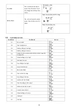
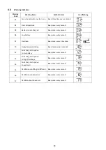
Warning Indicator 


Warning 

Code 

Warning Event 

Audible Alarm 

Icon flashing 

01 

Fan is locked when inverter is on. 

Beep three times every second 


02 

  Over temperature 

Beep once every second 


03 

Battery is over-charged 

Beep once every second 


04 

Low battery 

Beep once every second 


07 

Overload 

Beep once every 0.5 second 


10 

Output power derating 

Beep twice every 3 seconds 


12 

Solar charger stops due 

to low battery 

Beep once every second 


13 

Solar charger stops due 

to high PV voltage 

Beep once every second 


14 

Solar charger stops due 

to overload 

Beep once every second 


15 

Parallel input utility grid different 

Beep once every second 


16 

Parallel input phase error 

Beep once every second 


17 

Parallel output phase loss 

Beep once every second 


Содержание CPS3000ECH48A

Страница 1: ...ALL IN ONE OFF GRID INVERTER User s Manual CPS3000ECH48A CPS5000ECH48A CPS5000ECH48A P ...

Страница 2: ......

Страница 3: ...g the Unit 5 3 4 Battery Connection 6 3 5 AC Input Output Connection 8 3 6 PV Connection 9 3 7 Final Assembly 10 3 8 Communication Connection 11 3 9 Dry Contact Signal 11 3 10 Parallel installation Only CPS5000ECH48A P available 12 4 Operation 21 4 1 Power ON OFF 21 4 2 Operation and Display Panel 21 4 3 Display Setting 28 4 4 Operating Mode Description 31 4 5 Fault Reference Code 32 4 6 Warning I...

Страница 4: ... is operated Training in how to deal with the dangers and risks associated with installing and using electrical devices and installations Training in the installation and commissioning of electrical devices and installations Knowledge of the applicable standards and directives Knowledge of and compliance with this document and all safety information 1 3 Symbols Used Symbol Description WARNING indi...

Страница 5: ...propriate cable size It s very important to correctly operate this inverter 8 Please strictly follow installation procedure when you want to disconnect AC or DC terminals Please refer to installation section of this manual for the details 9 Grounding Instructions This inverter should be connected to a permanent grounded wiring system Be sure to comply with local requirements and regulation to inst...

Страница 6: ...id Please consult with your system integrator for other possible system architectures depending on your requirements The WiFi module is a plug and play monitoring device to be installed on the inverter With this device users can monitor the status of the PV system from the mobile phone or from the website anytime anywhere 2 1 Features Power factor 1 MPPT solar charge controller High frequency inve...

Страница 7: ...indicator 3 Charging indicator 4 Fault indicator 5 Function buttons 6 AC input 7 WiFi communication port 8 USB communication port 9 Dry contact 10 PV input 11 Power on off switch 12 Battery input 13 Parallel communication ports only for parallel model 14 Current sharing ports only for parallel model 15 AC output 16 Circuit breaker ...

Страница 8: ...s shown below 3 3 Mounting the Unit Consider the following points before selecting where to install Do not mount the inverter on flammableconstruction materials Mount on a solid surface Install this inverter at eye level in order to allow theLCD display to be read at all times The ambient temperature should be between 0 C and55 C to ensure optimal operation The recommended installation position is...

Страница 9: ...peration and regulation compliance it s requested to install a separate DC over current protector or disconnect device between battery and inverter It may not be requested to have a disconnect device in some applications however it s still requested to have over current protection installed Please refer to typical amperage in below table as required fuse or breaker size All wiring must be performe...

Страница 10: ...2 3 Nm Make sure polarity at both the battery and the inverter or charge is correctly connected and ring terminals are tightly screwed to the battery terminals Do not place anything between the flat part of the inverter terminal and the ring terminal Otherwise overheating may occur Do not apply anti oxidant substance on the terminals before terminals are connected tightly Before making the final D...

Страница 11: ...d tightenterminal screws Be sure to connect PE protective conductor first Ground yellow green L LINE brown or black N Neutral blue Before connecting to AC input power source please install a separate AC breaker between inverter and AC input power source This will ensure the inverter can be securely disconnected during maintenance and fully protected from over current of AC input The recommended sp...

Страница 12: ...rcuited when these inverters are worked in parallel operation Appliances such as air conditioner are required at least 2 3 minutes to restart because it s required to have enough time to balance refrigerant gas inside of circuits If a power shortage occurs and recovers in a short time it will cause damage to your connected appliances To prevent this kind of damage please check with manufacturer of...

Страница 13: ...n cable from PV modules and PV input connectors Then connect positive pole of connection cable topositive pole of PV input connector Connect negative pole of connection cable to negative pole of PV input connector 3 Make sure the wires are securely connected 3 7 Final Assembly After connecting all wiring please put bottom cover back by screwing two screws as shown below ...

Страница 14: ...red from Utility Close Open Output is powered from Battery or Solar Program 01 set as Utility Battery voltage Low DC warning voltage Open Close Battery voltage Setting value in Program 13 or battery charging reaches floating stage Close Open Program 01 is set as SBU or Solar first Battery voltage Setting value in Program 12 Open Close Battery voltage Setting value in Program 13 or battery charging...

Страница 15: ...themselves This installation steps are only applied to CPS5000ECH48A P model Step 1 Remove wire cover by unscrewing all screws Step 2 Remove communication board by unscrewing two screws as below chart Step 3 Remove two screws as below chart and remove 2 pin and 14 pin cables Take out the board under the communication board Step 4 Remove two screws as below chart to take out cover of parallel commu...

Страница 16: ...t wire cover back to the unit Now the inverter is providing parallel operation function 3 10 2 Mounting the Unit When installing multiple units please follow below chart NOTE For proper air circulation to dissipate heat allow a clearance of approx 20cm to the side and approx 50 cm above and below the unit Be sure to install each unit in the same level ...

Страница 17: ... inverters in parallel Power Connection Communication Connection 3 inverters in parallel Power Connection Communication Connection All inverters must be connected to the same batteries and ensure each group of cables from the inverters to the batteries in the same length WARNING ...

Страница 18: ...15 4 inverters in parallel Power Connection Communication Connection 5 inverters in parallel Power Connection Communication Connection ...

Страница 19: ... necessary to turn off switch when setting LCD program Otherwise the setting cannot be programmed Step 3 Turn on each unit LCD display in Master unit LCD display in Slave unit NOTE Master and slave units are randomly defined Step 4 Switch on all AC breakers of Line wires in AC input It s better to have all inverters connect to utility at the same time If not it will display warning 15 LCD display ...

Страница 20: ...hase system Two inverters in one phase and only one inverter for the remaining phases Power Connection Communication Connection All inverters must be connected to the same batteries and ensure each group of cables from the inverters to the batteries in the same length Do not connect the current sharing cable between the inverters which are in different phases Otherwise it may damage the inverters ...

Страница 21: ...1 Two inverters in two phases and only one inverter for the remaining phase Power Connection Communication Connection Type 2 Three inverters in one phase and only one inverter for the remaining two phases Power Connection Communication Connection ...

Страница 22: ...se system Type 1 Two inverters in each phase Power Connection Communication Connection Type 2 Three inverters in one phase two inverters in second phase and one inverter for the third phase Power Connection Communication Connection ...

Страница 23: ...lay in L2 phase unit LCD display in L3 phase unit Step 4 Switch on all AC breakers of Line wires in AC input If AC connection is detected and three phases are matched with unit setting they will work normally Otherwise if will display warning 15 16 and they will not work in the line mode LCD display in L1 phase unit LCD display in L2 phase unit LCD display in L3 phase unit Step 5 If there is no mo...

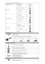
Страница 24: ...t output power information 1 LCD display 2 Status indicator 3 Charging indicator 4 Fault indicator 5 Function buttons LED Indicator LED Indicator Messages Green Solid On Output is powered by utility in Line mode Flashing Output is powered by battery or PV in battery mode Green Solid On Battery is fully charged Flashing Battery is charging Red Solid On Fault occurs in the inverter Flashing Warning ...

Страница 25: ... input voltage input frequency PV voltage battery voltage and charger current Configuration Program and Fault Information Indicates the setting programs Indicates the warning and fault codes Warning Flashing with warning code Fault Lighting with fault code Output Information Indicate output voltage output frequency load percent load in VA load in Watt and discharging current Battery Information In...

Страница 26: ... overload Indicates the load level by 0 24 25 49 50 74 and 75 100 0 24 25 49 50 74 75 100 Mode Operation Information Indicates unit connects to the mains Indicates unit connects to the PV panel Indicates load is supplied by utility power Indicates the utility charger circuit is working Indicates the DC AC inverter circuit is working These three signs indicate the output priority SOL FIRST indicate...

Страница 27: ...loads as first priority Solar and battery energy will provide power to the loads only when utility power is not available SBU priority Solar energy provides power to the loads as first priority If solar energy is not sufficient to power all connected loads battery energy will supply power to the loads at the same time Utility provides power to the loads only when battery voltage drops to either lo...

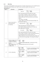
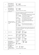
Страница 28: ... low DC cut off voltage can be set up in program 19 20 and 21 Flooded Lithium Only suitable when communicated with BMS 06 Auto restart when overload occurs Restart disable default Restart enable 07 Auto restart when over temperature occurs Restart disable default Restart enable 08 Output voltage 230V default 220V 240V 208V 09 Output frequency 50Hz default 60Hz 10 Number of series batteries connect...

Страница 29: ...rgy will charge battery only when utility power is not available Solar and Utility Solar energy and utility will both charge battery Only Solar Solar energy will be the only charger source no matter utility is available or not If this inverter is working in Battery mode or Power saving mode only solar energy can charge battery Solar energy will charge battery if it s available and sufficient 15 Al...

Страница 30: ...Single When the units are used in parallel with single phase please select PAL in program 23 It requires 3 inverters to support three phase equipment 1 inverter in each phase Please refers to 5 2 for detailed information Please select 3P1 in program 23 for the inverters connected to L1 phase 3P2 in program 23 for the inverters connected to L2 phase and 3P3 in program 23 for the inverters connected...

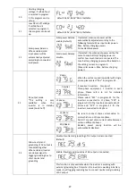
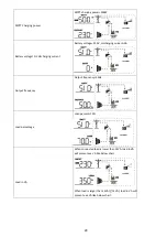
Страница 31: ...ging current MPPT charging power battery voltage output voltage output frequency load percentage load in VA load in Watt DC discharging current main CPU Version and second CPU Version Setting Information LCD display Input voltage Output voltage Default Display Screen Input Voltage 230V output voltage 230V Input frequency Input frequency 50Hz PV voltage PV voltage 60V Charging current Current 10A C...

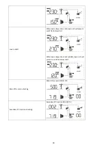
Страница 32: ...ery voltage 51 0V discharging current 0A Output frequency Output frequency 50Hz Load percentage Load percent 70 Load in VA When connected load is lower than 1kVA load in VA will present xxx VA like below chart When load is larger than 1kVA 1KVA load in VA will present x x kVA like below chart ...

Страница 33: ... load in W will present xxx W like below chart When load is larger than 1kW 1KW load in W will present x x kW like below chart Main CPU version checking Main CPU version 500 00 719 Secondary CPU version checking Secondary CPU version 002 00 719 ...

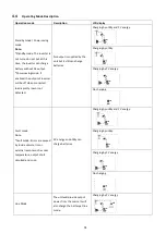
Страница 34: ...s supplied by the unit but it still can charge batteries Charging by utility and PV energy Charging by utility Charging by PV energy No charging Fault mode Note Fault mode Errors are caused by inside circuit error or external reasons such as over temperature output short circuited and so on PV energy and utility can charge batteries Charging by utility and PV energy Charging by utility Charging by...

Страница 35: ... 01 Fan is locked 02 Over temperature 03 Battery voltage is too high 04 Battery voltage is too low 05 Output short circuited is detected by internal converter components 06 Output voltage is too high 07 Overload time out 08 Bus voltage is too high 09 Bus soft start failed 11 Main relay failed 51 Over current or surge 52 Bus voltage is too low 53 Inverter soft start failed 55 Over DC voltage in AC ...

Страница 36: ...very second 07 Overload Beep once every 0 5 second 10 Output power derating Beep twice every 3 seconds 12 Solar charger stops due to low battery Beep once every second 13 Solar charger stops due to high PV voltage Beep once every second 14 Solar charger stops due to overload Beep once every second 15 Parallel input utility grid different Beep once every second 16 Parallel input phase error Beep on...

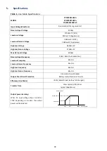
Страница 37: ...put Voltage 300Vac Nominal Input Frequency 50Hz 60Hz Auto detection Low Loss Frequency 40 1Hz Low Loss Return Frequency 42 1Hz High Loss Frequency 65 1Hz High Loss Return Frequency 63 1Hz Output Short Circuit Protection Line mode Circuit Breaker Battery mode Electronic Circuits Efficiency Line Mode 95 Rated R load battery full charged Transfer Time 10ms typical UPS 20ms typical Appliances Output p...

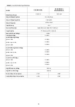
Страница 38: ...10s 110 150 load Surge Capacity 2 rated power for 5 seconds Nominal DC Input Voltage 48Vdc Cold Start Voltage 46 0Vdc Low DC Warning Voltage 44 0Vdc 42 8Vdc 40 4Vdc load 20 20 load 50 load 50 Low DC Warning Return Voltage 46 0Vdc 44 8Vdc 42 4Vdc load 20 20 load 50 load 50 Low DC Cut off Voltage 42 0Vdc 40 8Vdc 38 4Vdc load 20 20 load 50 load 50 High DC Recovery Voltage 56 4Vdc High DC Cut off Volt...

Страница 39: ...A 40 50 60A Bulk Charging Voltage Flooded Battery 58 4Vdc AGM Gel Battery 56 4Vdc Floating Charging Voltage 54Vdc Overcharge Protection 60Vdc Charging Algorithm 3 Step Charging Curve Battery Voltage per cell Charging Current 2 43Vdc 2 35Vdc Voltage 2 25Vdc 100 50 T0 T1 T1 10 T0 minimum 10mins maximum 8hrs Current Time Bulk Absorption Maintenance Constant Current Constant Voltage Floating ...

Страница 40: ...y Voltage Accuracy 0 3 PV Voltage Accuracy 2V Charging Algorithm 3 Step Joint Utility and Solar Charging Max Charging Current 45Amp 140Amp Default Charging Current 30Amp 60Amp Table 4 General Specifications MODEL CPS3000ECH48A CPS5000ECH48A CPS5000ECH48A P Safety Certification CE Operating Temperature Range 0 C to 55 C Storage temperature 15 C 60 C Humidity 5 to 95 Relative Humidity Non condensing...

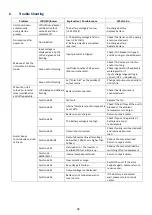
Страница 41: ...al relay is switched on and off repeatedly LCD display and LEDs are flashing Battery is disconnected Check if battery wires are connected well Buzzer beeps continuously and red LED is on Fault code 01 Fan fault Replace the fan Fault code 02 Internal temperature of component is over 100 C Check if the air flow of the unit is blocked or the ambient temperature is too high Fault code 03 Battery is ov...

Страница 42: ...39 Note ...

Страница 43: ...40 Note ...

Страница 44: ...www CyberPower com K01 TP11001 01 ...

Отзывы: